
Lab 9: Timers and time-based interrupts
1. Timers with polling
Suppose you want to flash two LEDs at different rates. There is no good way to do this with k_msleep commands (or PWM outputs because the PWM peripheral can only have one period for all of its outputs). One solution to this is to use a timer with polling.
We will just use the internal LEDs so no additional circuit is required (or overlay, or prj.conf). All you need to do is create an application with the code in Program 1.
#include <zephyr/kernel.h>
#include <zephyr/drivers/gpio.h>

#define LED0_NI DT_ALIAS(led0)
#define LED1_NI DT_ALIAS(led1)
const struct gpio_dt_spec fast_led = GPIO_DT_SPEC_GET(LED0_NI, gpios);
const struct gpio_dt_spec slow_led = GPIO_DT_SPEC_GET(LED1_NI, gpios);

K_TIMER_DEFINE(fast_timer, NULL, NULL); (1)
K_TIMER_DEFINE(slow_timer, NULL, NULL);

int main(void) {
    gpio_pin_configure_dt(&fast_led, GPIO_OUTPUT_ACTIVE);
    gpio_pin_configure_dt(&slow_led, GPIO_OUTPUT_ACTIVE);

    k_timer_start(&fast_timer, K_MSEC(75), K_MSEC(75)); (2)
    k_timer_start(&slow_timer, K_MSEC(1700), K_MSEC(1700));

    while (true) {
        if (k_timer_status_get(&fast_timer) > 0) { (3)
            gpio_pin_toggle_dt(&fast_led);
        }
        if (k_timer_status_get(&slow_timer) > 0) {
            gpio_pin_toggle_dt(&slow_led);
        }
    }
}| 1 | The K_TIMER_DEFINE macro is used to define a timer. The first parameter is the name of the timer, the second is the callback function to be called when the timer reaches its timeout value, and the third is the callback function to be called if the timer is stopped. In this case we are not using callbacks so we pass NULL for both. |
| 2 | The timer is started with an initial timeout of 75 ms and a recurring timeout of 75 ms. |
| 3 | The k_timer_status_get function returns the number of times the timer has reached its timeout value since last checked. If the return value is greater than 0, it has passed the timeout value. |
Modify Program 1 so it flashes all four of the internal LEDs using timers with polling to control the flashing. LED3 should toggle its state every 0.5 seconds and LED4 should toggle every 1.3 seconds.
| When your program and circuit are working successfully, demonstrate this. |
2. Introduction to callback functions
Instead of using a timer and polling to flash an LED, you can use a callback function that will automatically be triggered when the timer reaches a timeout. The toggling of the LED now takes place in an interrupt service routine (ISR), not in normal program context.
We will just use the internal LEDs so no additional circuit is required. You do need to configure the logging module in prj.conf (code not shown because you should know how to do that by now) in a new application. All that remains is to enter the code in Program 2.
#include <zephyr/kernel.h>
#include <zephyr/drivers/gpio.h>
#include <zephyr/logging/log.h>

#define LED0_NI DT_ALIAS(led0)
#define LED1_NI DT_ALIAS(led1)
const struct gpio_dt_spec fast_led = GPIO_DT_SPEC_GET(LED0_NI, gpios);
const struct gpio_dt_spec slow_led = GPIO_DT_SPEC_GET(LED1_NI, gpios);

void toggler_fast(struct k_timer *timer); (1)
void toggler_slow(struct k_timer *timer);
K_TIMER_DEFINE(fast_timer, toggler_fast, NULL); (2)
K_TIMER_DEFINE(slow_timer, toggler_slow, NULL);

volatile int fastCount; (3)
volatile int slowCount;

LOG_MODULE_REGISTER(Lab9b, LOG_LEVEL_INF);

int main(void) {
    fastCount = 0; (4)
    slowCount = 0;

    gpio_pin_configure_dt(&fast_led, GPIO_OUTPUT_ACTIVE);
    gpio_pin_configure_dt(&slow_led, GPIO_OUTPUT_ACTIVE);

    k_timer_start(&fast_timer, K_MSEC(75), K_MSEC(75));
    k_timer_start(&slow_timer, K_MSEC(1700), K_MSEC(1700));

    while (true) { (5)
        LOG_INF("Fast toggles = %d and slow toggles = %d", fastCount, slowCount);
        k_sleep(K_MSEC(5000));
    }
}

void toggler_fast(struct k_timer *timer) {
    gpio_pin_toggle_dt(&fast_led);
    if (gpio_pin_get_dt(&fast_led)) fastCount++; (6)
}

void toggler_slow(struct k_timer *timer) {
    gpio_pin_toggle_dt(&slow_led);
    if (gpio_pin_get_dt(&slow_led)) slowCount++;
}| 1 | The prototype for the callback function to be used by the fast timer is declared. |
| 2 | The fast timer is defined with the callback function toggler_fast. |
| 3 | Two global variables are declared to keep track of the number of times each LED has been toggled. These are declared as volatile because they are modified in an ISR. The volatile keyword tells the compiler that the variable can be changed by something outside the normal flow of the program. |
| 4 | The global variables are initialized to 0. |
| 5 | The main loop prints the number of times each LED has been toggled every 5 seconds. This is done to demonstrate that the toggling is happening in the background. |
| 6 | The global variables are incremented each time the LED is toggled back to the on state. |
Modify Program 2 by create a timer-has-stopped callback that turns off the fast LED in the event that the fast timer is stopped and prints a log message about being stopped.
After you have done that, modify the while loop in main so it stops after 10 on-off cycles of the slow LED. After exiting the while loop, the fast timer should be stopped. The slow LED should continue to flash until the program is reset.
| When your program and circuit are working successfully, demonstrate this. |
3. Introduction to one-shot timers
When an external button is pushed, it will turn on a green LED. A timer will be activated to turn that LED off after two seconds. To illustrate how ISRs interact with normal program context, a red LED will be blinked off-and-on in the primary while loop using our old-style sleep approach.
-
Connect a red LED and 330 Ω resistor in series between P0.29 and ground.
-
Connect a green LED and 330 Ω resistor in series between P0.28 and ground.
-
Connect a button so that it connects P0.03 to VDD when pressed.
-
Create a new application with an overlay that allows the use of P0.28 and P0.29 to control the LEDs. The button portion of the overlay defines P0.03 as an input and should also enable the internal pull-down resistor.
-
Enter the code of Program 3 into
main.c. -
Build and flash the application to your nRF52840 DK.
#include <zephyr/kernel.h>
#include <zephyr/drivers/gpio.h>

#define SLEEP_TIME_MS   300

#define RED_NI DT_NODELABEL(redled)
#define GREEN_NI DT_NODELABEL(greenled)
#define BTN_NI DT_NODELABEL(pb)
const struct gpio_dt_spec redLED = GPIO_DT_SPEC_GET(RED_NI, gpios);
const struct gpio_dt_spec greenLED = GPIO_DT_SPEC_GET(GREEN_NI, gpios);
const struct gpio_dt_spec btn = GPIO_DT_SPEC_GET(BTN_NI, gpios);

void alertOff(struct k_timer *timer);
K_TIMER_DEFINE(alert_timer, alertOff, NULL);

int main(void) {
    gpio_pin_configure_dt(&redLED, GPIO_OUTPUT_ACTIVE);
    gpio_pin_configure_dt(&greenLED, GPIO_OUTPUT_INACTIVE);
    gpio_pin_configure_dt(&btn, GPIO_INPUT);

    while (true) {
        if (gpio_pin_get_dt(&btn)) {
            gpio_pin_set_dt(&greenLED, 1);
            k_timer_start(&alert_timer, K_MSEC(2000), K_FOREVER); (1)
        }
        gpio_pin_toggle_dt(&redLED);
        k_msleep(SLEEP_TIME_MS);
    }
}

void alertOff(struct k_timer *timer) {
    gpio_pin_set_dt(&greenLED, 0);
}| 1 | The one-shot timer is started with an initial timeout of 2 seconds and a recurring timeout of forever (i.e., it will not repeat). |
You will now use the Analog Discovery 2 oscilloscope to understand the behavior of Program 3.
-
Connect
 to the ground bus.
 -
Connect 1+ to the junction between P0.28 and the green LED/resistor combo and 1- to ground.
-
Connect 2+ to the junction between the button and P0.03 and 2- to ground.
-
In the oscilloscope app, make the following Trigger settings:
-
Mode = Normal
-
Level = 2 V
-
-
In the Time settings, set Base to 1 s/div. In the settings for both Channel 1 and 2, set the offset to -2 V and the range to 500 mV/div.
-
Click the Single acquisition button and wait for the oscilloscope display to show the message “Armed” in the upper left of the graph (next to C1 and C2). Once it is armed, push the momentary push button (just a quick push and release). If the green LED doesn’t turn on, continue with a series of quick pushes (roughly 0.5 s pauses between them) until it does turn on. Wait patiently for the oscilloscope capture to display.
-
The blue trace shows the button voltage and the yellow trace is the green LED voltage. You should notice that the yellow trace goes high while the blue trace is high. If it took more than one button push to activate the green LED, you should see those previous attempts as well.
-
The yellow trace should remain high for two seconds. Verify this using the PosWidth measurement on channel 1.
-
You will at the variability of this behavior. Repeat the Single acquisition 4 more times and pay attention to the LED “on” time. Do you get 2.0000 s each time?
-
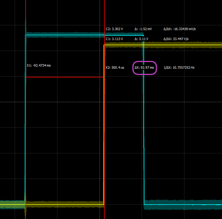
You will now look at the time of the LED activation in more detail. Change the Time base to 50 ms/div and click Single followed by pushing the momentary push button until you get an oscilloscope capture.
-
Turn on the Quick Measure: Horizontal tool by clicking on its icon in the upper right of the oscilloscope graph.
-
Click on the left side of the blue trace transition from low to high (this marks the instant the button was first pushed down). Now move right until the vertical red line (usually called a cursor in the context of oscilloscope measurements) indicates you are over the off-to-on transition for the LED. You should see something like the following:
-
The time from when the button was pushed to when the LED was activated is display as ΔX by this tool. Record this time, called the latency, on your Lab 9 worksheet.
-
Repeat this measurement process (acquire, adjust vertical cursor, and record latency) nine more times.
-
Summarize these results by identifying the maximum latency, the minimum latency, and the average latency.
Leave this circuit in place. You will be using it again.
4. Your Turn
4.1. Temperature averager
In this assignment you will demonstrate your ability to use time-based interrupts and arrays.
Get the link to the template on Canvas.
You will use the TMP36 analog temperature sensor to record the temperature (in Fahrenheit) once every 5 seconds. When a button is pushed all of the saved temperatures (up to a maximum of 12) should be printed to the screen as well as their average value. This event also clears the memory. When 12 temperatures have been saved, an LED should be lit to indicate that the temperature buffer has reached its maximum capacity. If additional measurements are received, they should progressively replace the oldest ones such that only the twelve most recent measurements are retained. Remember, the “full buffer” LED should be turned off when the button is pressed.
You are to demonstrate your ability to use appropriate microcontroller design for responsive programming so should use timers with callbacks. You should also store the temperatures in an array.
| When your program and circuit are working, create a video demonstrating this. |