
Lab 4: Direct GPIO port writing and reading
1. Setting multiple pins on a GPIO port
We can think of the four internal LEDs on the nRF52840 DK as representing a 4-bit number because each LED as only two states (on and off). The value represented by a particular LED when it is turned on is given in Table 1. The advantage of this representation is that it becomes possible to set the state of all four LEDs with a single command rather than four commands that individually set each LED. All possible on-off combinations of the LEDs can be represented by an integer between 0 and 15. For example, the value of 10 (which can be expressed as 8+2) represents led3 and led1 turned on and the other two LEDs turned off.
| LED | Value as Power of 2 | Value |
|---|---|---|
|
20 |
1 |
|
21 |
2 |
|
22 |
4 |
|
23 |
8 |
This approach only works when the pins we wish to group are all connected to the same GPIO controller. There are two GPIO controller peripherals on the nRF52840 DK, labeled port 0 and port 1. This approach is also easier when the pins we wish to control have consecutive pin numbers. The four internal LEDs are connected to pins 13, 14, 15, and 16 of port 0 so we can use this method.
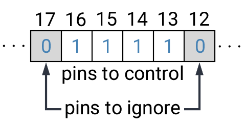
We only want to impact those particular pins and not others so a mask is used to specify that. There are 32 pins so a 32-bit integer is sufficient. The pins we wish to control are set to 1 in the mask and those to be left alone have a mask value of 0. Zephyr has a variable type gpio_port_value_t that more clearly tells the reader of the code that this particular integer is being used to store pin-by-pin values.
Zephyr also provides a macro called BIT that make setting these bits easier. The macro BIT(13) creates an integer in which bit 13 is set to 1 and the others are 0. We then combine those integers using C’s bit-wise OR operator, |. In a bit-wise operation the corresponding bits of the two numbers are compared. With bit-wise OR, a bit is 1 in the resulting integer if either of the two inputs had that bit set to 1.
-
Create a new application called
led-rotator. -
Enter the following code into
main.c.Program 1. Set state of multiple LEDs with single command.#include <zephyr/kernel.h> #include <zephyr/drivers/gpio.h> #include <zephyr/device.h> #include <zephyr/devicetree.h> #define SLEEP_TIME_MS 500 /* Get node identifier for the port rather than a particular pin */ #define PORT0_NI DT_NODELABEL(gpio0) /* Get device (more general than get a GPIO) */ const struct device *port = DEVICE_DT_GET(PORT0_NI); int main(void) { int led_on; gpio_port_value_t led_mask = BIT(13) | BIT(14) | BIT(15) | BIT(16); (1) if (device_is_ready(port)) { for (int pin = 13; pin <= 16; pin++) { gpio_pin_configure(port, pin, GPIO_OUTPUT_ACTIVE | GPIO_ACTIVE_LOW); (2) } } else return -1; while (true) { led_on = 0; while (led_on < 4) { gpio_port_set_masked(port, led_mask, BIT(led_on) << 13); (3) k_msleep(SLEEP_TIME_MS); led_on++; } } }1 This operation results in an integer with bits 13-16 set to 1 and all other bits set to zero. 2 We are directly accessing the pin rather than using its devicetree configuration. This means we need to explicitly specify information that was previously done for us through that configuration. In this case, the LEDs on the development board are connected so that they are active (on) when the voltage is low. 3 The left-bit-shift operator, <<, is used to move our four-bit led value to the left by 13 bits so it is now at bits 13-16 (the location of the pins on the port). -
Add the build configuration through the nRF Connect side bar and build the application.
-
Connect the development board to the computer and then use the Flash action to send the program to it.
-
You should observe that LEDs 1 through 4 are lit one at a time and the program continuously rotates through these.
2. Reading multiple pins on a GPIO port
We can read the state of all of the pins in a GPIO port, with each pin represented as one bit of a 32-bit integer. The four buttons are not contiguous (they are at pins 11, 12, 24, and 25) so to determine whether a particular button is pressed we use bit-wise AND (&) to test whether the corresponding bit is set. In a bit-wise AND, the resulting integer has the corresponding bit equal to 1 only if both of the inputs had that bit set to 1.
We are not relying on devicetree configuration of the buttons here so we need to do more than say that they are inputs. We also need to specify the details of their hardware connection (low voltage when pressed, with an internal pull-up resistor required to create the proper logic).
-
Create a new application called
read-all-buttons. -
Enter the following code into
main.c.1 Each time through the loop, set the led value variable back to zero. 2 If the button corresponding to a particular LED is pushed, set the bit for that LED to 1. -
Add the build configuration through the nRF Connect side bar and build the application.
-
Connect the development board to the computer and then flash the program to it.
-
You should observe that LEDs 1 through 4 are lit when the corresponding button is pushed. It is possible to have multiple LEDs lit at the same time if multiple buttons are simultaneously pushed down.
3. Seven-segment display
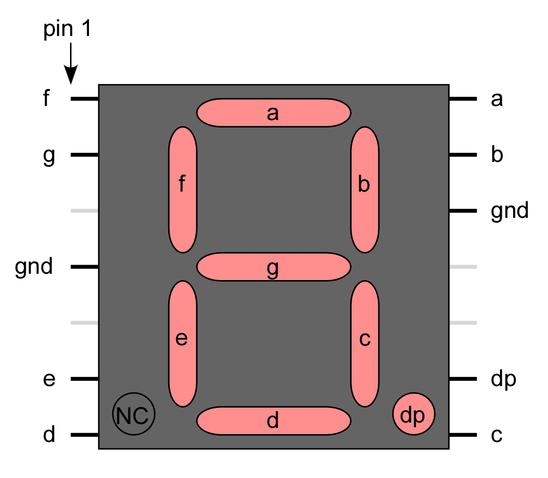
A seven-segment display is a collection of LEDs that is designed to display a decimal digit when the appropriate segments are activated. We are using a LIGITEK LSD3211 that has the pin configuration shown in Figure 2.
-
Place the seven-segment display in a breadboard, being sure that it straddles the trench (so pins on the left side are not connected to pins on the right side).
-
Next, connect the microcontroller ground (one of the pins labelled GND) to the ground bus strip.
-
Connect both of the pins labeled gnd on the seven-segment display to the ground bus strip.
-
Next, connect the nRF52840 DK pins P1.01 through P1.07 to the seven-segment display pins, starting with a and going through g. We will leave dp unconnected.
-
After you have assembled this circuit on the breadboard, create a new application.
-
No devicetree overlay is required because we are using direct GPIO port writes. The disadvantage is that the documentation of which pins are being used is less clear.
-
Enter Program 3 into
main.c.Program 3. Show digits 0 to 3 on seven-segment display.#include <zephyr/kernel.h> #include <zephyr/drivers/gpio.h> #include <zephyr/device.h> #include <zephyr/devicetree.h> #define SLEEP_TIME_MS 750 #define PORT1_NI DT_NODELABEL(gpio1) const struct device *port = DEVICE_DT_GET(PORT1_NI); int main(void) { int pin_mask = BIT(1) | BIT(2) | BIT(3) | BIT(4) | BIT(5) | BIT(6) | BIT(7); int display; if (device_is_ready(port)) { for (int pin = 1; pin <= 7; pin++) { gpio_pin_configure(port, pin, GPIO_OUTPUT_INACTIVE); } } else return -1; while (true) { for (int i = 0; i<4; i++) { switch(i) { case 0: display = 0x3F; break; case 1: display = 0x06; break; case 2: display = 0x5B; break; case 3: display = 0x4F; break; } gpio_port_set_masked(port, pin_mask, display << 1); k_msleep(SLEEP_TIME_MS); } } } -
Build the application and flash it to your microcontroller. If everything has been done correctly, you should see the digits 0 through 3 displayed one at a time.
4. Introduction to functions
The basic format of a program to control a seven-segment display with a function to convert digits to hex codes is shown in Program 4. We will use functions for sections of code that might be reused in other contexts and/or to break code into units that make the logic more transparent.
#include <zephyr/kernel.h>
#include <zephyr/drivers/gpio.h>
#include <zephyr/device.h>
#include <zephyr/devicetree.h>

int sevenSegConvert(int n);

#define SLEEP_TIME_MS   750

#define PORT1_NI DT_NODELABEL(gpio1)
const struct device *port = DEVICE_DT_GET(PORT1_NI);

int main(void) {
    int pin_mask = BIT(1) | BIT(2) | BIT(3) | BIT(4) | BIT(5) | BIT(6) | BIT(7);
    int display;

    if (device_is_ready(port)) {
        for (int pin = 1; pin <= 7; pin++) {
            gpio_pin_configure(port, pin, GPIO_OUTPUT_INACTIVE);
        }
    } else return -1;

    while (true) {
        for (int i = 0; i<= 9; i++) {
            gpio_port_set_masked(port, pin_mask, sevenSegConvert(i) << 1);
            k_msleep(SLEEP_TIME_MS);
        }
    }
}

int sevenSegConvert(int n) {
  // function code

  return display;
}Fill in the details of the sevenSegConvert function in Program 4 so it returns the correct control values for the digits 0 through 9.
| When your program and circuit are working successfully, demonstrate this to the instructor. |
5. Your Turn
|
The directions that follow are intended for students in my Introduction to Embedded Systems course at Whitworth University. However, an alternative link to a template is provided for non-Whitworth students. |
Your task is to create a system that counts “letters” using a photointerrupter, displaying the count on a seven-segment display. If a count greater than 9 occurs, turn on an internal LED to indicate that the true count is 10 plus whatever is displayed on the seven-segment display. This allows your application to indicate counts up to 19. An internal button is used to send a log message with the total count and then reset the count to zero.
-
Access the GitHub Classroom link for this assignment on Canvas and create a repository for your work.
If you are not a Whitworth student in EN 173 you may access a starting template at https://github.com/EmbedUni/lab04-yt1. You will want to click on the Use this template button. -
A code repository was created when you accessed the assignment. Copy the URL for the repository.
-
Open the Source Control side bar in VS Code and clone the repository.
-
Generate a build configuration and devicetree overlay. In the overlay file, add the code needed to configure the photointerrupter.
-
Edit the
prj.conffile to include the necessary settings for logging. -
Assemble the photointerrupter circuit on a breadboard.
-
Assemble the seven-segment display circuit the same breadboard.
-
Modify
main.cso it accomplishes the task described above. -
Test your program.
-
Update the
README.md.
| When your program and circuit are working successfully, remember to push the commits to the remote repository. Also, take a video of its successful operation and upload this to Canvas. |