
Lab 2: Basic Digital Input and Output
1. Internal buttons
The nRF52840 DK board has five buttons. The button set off by itself resets the board. The four buttons in a cluster are ones available for use in our code. On the board they have labels BUTTON1 through BUTTON4, but their aliases in code are sw0 through sw3. If you have not encountered it before, sw is a common abbreviation for switch in electronics.
-
Create a new application called
led-enabler. -
Enter the following code into
main.c.Program 1. Use a button to turn on an LED.#include <zephyr/kernel.h> #include <zephyr/drivers/gpio.h> #define SLEEP_TIME_MS 100 /* Get node identifiers for hardware */ #define LED0_NI DT_ALIAS(led0) #define BTN0_NI DT_ALIAS(sw0) (1) /* Get gpio specs */ const struct gpio_dt_spec led = GPIO_DT_SPEC_GET(LED0_NI, gpios); const struct gpio_dt_spec button = GPIO_DT_SPEC_GET(BTN0_NI, gpios); (2) int main(void) { int btn_pressed; (3) if (gpio_is_ready_dt(&led)) { (4) gpio_pin_configure_dt(&led, GPIO_OUTPUT_INACTIVE); } else { (5) return -1; (6) } if (gpio_is_ready_dt(&button)) { gpio_pin_configure_dt(&button, GPIO_INPUT); (7) } else { return -1; } while (true) { btn_pressed = gpio_pin_get_dt(&button); (8) gpio_pin_set_dt(&led, btn_pressed); (9) k_msleep(SLEEP_TIME_MS); } }1 The node identifier for BUTTON1 is obtained using its alias: sw0.2 Buttons, like LEDs, are controlled by GPIO pins. The process of getting the GPIO specifications is the same for buttons as it is for LEDs. 3 A integer variable is declared to hold the state of the button. 4 Although it was not done in the Lab 1 examples, it is best practice to always check that peripherals are ready before attempting to use them. The function gpio_is_ready_dtreturnstrueif the specified GPIO pin is ready. The code that follows in the curly braces will only be executed if the GPIO pin connected to the LED is ready for use.5 The elsestatement marks the beginning of code that will be executed ifgpio_is_ready_dtreturnsfalse.6 The returncommand causes themainfunction to be exited, sending a value of -1 to the kernel (the code that calledmainat startup). A return value of 0 is usually used to signal success and negative values indicate various types of errors.7 The pin connected to BUTTON1 is configured as an input. 8 The state of the button is read and its value (0 for released and 1 for pressed) is saved in the variable btn_pressed.9 The LED is set to have the same value as the button (on if pressed, off if released). -
Add the build configuration through the nRF Connect side bar and build the application.
-
Connect the development board to the computer and then use the Flash action to send the program to it.
-
Verify that LED1 is only lit while BUTTON1 is held down.
2. Controlling external LEDs
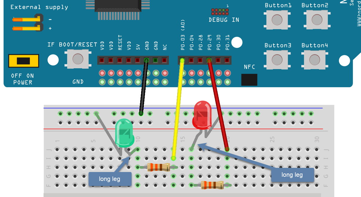
Light-emitting diodes (LEDs) do not have a constant resistance. For low voltages, they have a nearly infinite resistance (allow no current to flow). However, once the voltage exceeds a color-specific threshold, the resistance drops rapidly to nearly zero, allowing small changes in the voltage to create large changes in the current. If too much current flows through the LED, it will overheat and die. To prevent this, we will almost always connect a resistor in series with the LED. A 330 Ω resistor keeps the current to a safe level for the LEDs we will be using and with the voltage that our microcontroller can supply. A 330 Ω resistor has the color bands orange-orange-brown. The gold band indicates that the manufacturer guarantees that the actual resistance is within 5% of the indicated value.
LEDs are also unidirectional devices. That is, they have a preferred direction for the flow of current. It takes a much larger voltage to cause a current to flow the “wrong” way (and the LED won’t usually survive the experience if it does manage to happen). To help us know which direction they should be connected, manufacturers almost always make the legs of LEDs different lengths. The longer leg goes on the side closer to the higher voltage and the shorter leg goes on the side closer to ground.
Construct the circuit shown in Figure 1 on your breadboard. The ground connection (one of the header sockets marked GND on the development board) should be connected to the bus strip that is marked with the blue (or black, depending on the breadboard manufacturer) line. We will be consistent about doing this throughout the course because it will make debugging your circuits easier (and it is the convention in this field). The apparent lengths of the LED legs in this diagram are solely due to how far they had to travel to reach their proper holes. So, even though it appears that a longer leg is attached to the ground bus strip, that is not the case. The short leg of each LED should be connected to the ground bus.
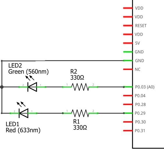
Professionals would never draw a picture like Figure 1 to show how a circuit is connected. Instead, a more abstract circuit diagram would be used. The diagram in Figure 2 is how they would draw this circuit.
Assembly this circuit on the breadboard.
2.1. Application code and hardware overlay
-
Create a new application called
external-leds. -
Enter Program 2 into
main.c.Program 2. Flash red and green LED in an alternating pattern.#include <zephyr/kernel.h> #include <zephyr/drivers/gpio.h> #define SLEEP_TIME_MS 200 /* Get node identifiers for hardware */ #define RED_NI DT_ALIAS(redled) #define GREEN_NI DT_ALIAS(greenled) /* Get gpio specs */ const struct gpio_dt_spec redLED = GPIO_DT_SPEC_GET(RED_NI, gpios); const struct gpio_dt_spec greenLED = GPIO_DT_SPEC_GET(GREEN_NI, gpios); int main(void) { if (gpio_is_ready_dt(&redLED)) { gpio_pin_configure_dt(&redLED, GPIO_OUTPUT_ACTIVE); } else { return -1; } if (gpio_is_ready_dt(&greenLED)) { gpio_pin_configure_dt(&greenLED, GPIO_OUTPUT_INACTIVE); } else { return -1; } while (true) { gpio_pin_toggle_dt(&redLED); gpio_pin_toggle_dt(&greenLED); k_msleep(SLEEP_TIME_MS); } } -
Select Add build configuration panel through the nRF Connect side bar and select our board as the target. In a change from past procedure, check the Generate only box. This will change the final button to Generate. Click on this button.
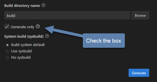 Figure 3. Generate the configuration but do not build the application.
 -
In the APPLICATIONS section of the nRF Connect side panel, select the entry for your particular build configuration under the build subsection (it should be named something like
external-leds - nRF52840 DK nRF52840). -
In the EXTERNAL-LEDS section of the nRF Connect side panel, expand the Config files entry and then the Devicetree entry below that. You should see an item labeled
nrf52840dk_nrf52840.dtsand below that a + Create overlay file item. Click on the Create overlay item. -
If you look in the files for your application, you should now see a new file named
nrf52840dk_nrf52840.overlay. Add the following to that file.Program 3. The overlay file allows us to configure pins for use./{ leds { (1) red_led: led_4 { (2) gpios = <&gpio0 29 GPIO_ACTIVE_HIGH>; (3) }; green_led: led_5 { gpios = <&gpio0 3 GPIO_ACTIVE_HIGH>; }; }; aliases { redled = &red_led; (4) greenled = &green_led; }; };1 We are adding entries to the ledssection of the devicetree for this board.2 Our first new entry is a subnode with the name led_4and a label ofred_led.3 The red LED will be connected to P0.29. P0 is short for GPIO port 0, which in this code is identified by &gpio0. This is pin 29 connected to that port. The LED will be lit when the output of this pin is the high voltage state (around 3 V).4 Defining the alias that will be used to access this using DT_ALIASinmain.c. -
You now want to perform a pristine build (a more complete build process that is required after altering the devicetree description of the hardware). The pristine build option can be found in the Actions section of the nRF Connect side panel. Hovering over Build will reveal the pristine build icon (a circular arrow) on the right. Click on this icon.
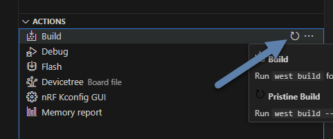 Figure 4. The pristine build icon appears on the right hand side of the Build action upon hovering.
 -
Use the Flash action to send the program to your board. If everything has been done correctly, you should see lit red and green LEDs alternating.
2.2. Documenting the code
Remember, documentation is an essential part of good coding. Create a README.md file and enter Program 4. Notice that this has a section for external hardware that briefly describes how that is connected.
# Program: Red-Green Alternating LEDs
**Author:** John M. Larkin <jlarkin@whitworth.edu>
**Date:** December 31, 2024

**Modified by:**
**Date:**

**Purpose:** This program flashes two external LEDs.

## Configuration
Devicetree overlay sets:
* P0.29 as GPIO in `leds` group with alias `redled`
* P0.03 as GPIO in `leds` group with alias `greenled`

Both are set active high.

## Hardware
### External
* P0.29 --> red LED and 330 ohm resistor --> GND
* P0.03 --> green LED and 330 ohm resistor --> GND

## Flow
```mermaid
graph LR
A("main()") --> B[Initial state of red LED is on and green LED is off]
B--> C{Is it true?}
C --> |yes| D[Toggle state of both LEDs]
D --> E([Sleep 200 ms])
E --> C
```| Demonstrate that you have successfully assembled this circuit and downloaded this program. |
2.3. Exploring GPIO output with an oscilloscope
In this exercise you will use a compact oscilloscope, the Analog Discovery 2, to learn more about the voltages in this circuit. The results of your measurements should be written on the Exercise 2.1 worksheet and turned in when you are done.
-
Start by connecting an Analog Discovery 2 to a computer with the WaveForms program (freely available from Digilent).
-
Connect the flywire labeled 1+ (top left, orange) to the same column as the junction between the wire from P0.29 and the resistor. Connect the flywire labeled 1- (bottom left, orange with white stripe) to the ground bus strip. Also connect a flywire labeled ground (black wire) to the ground bus strip.
-
Start the WaveForms program. Click on the Scope button on the left side of the screen.
-
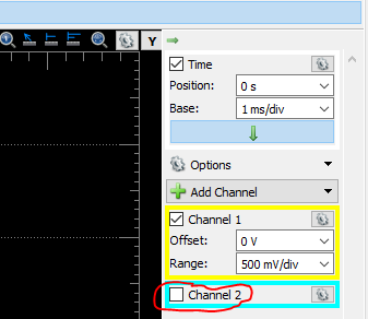
You are only using channel 1 of the oscilloscope so turn off the channel 2 display by unchecking its box on the right side of the screen, as shown below.
-
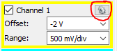
All of the voltages you will be measuring should be positive so we want the position of 0 volts to be at the bottom of the display, not at the center. To accomplish this, change the Channel 1 offset to -2 V.
-
Just above the channels settings are the time settings (the horizontal axis). Set Base to 50 ms/div.
-
The oscilloscope needs to know when to capture the voltage that will be displayed. This is done by setting a trigger condition (which channel to monitor, whether to activate on a rising or falling voltage, and at what particular voltage). We want channel 1, rising, and 1 V. The defaults should be channel 1 and rising so you only need to change the level in the trigger settings above the main display.

-
Click the Single acquisition button.

-
The main display should now have a bold yellow line that is tracing out the off-on-off pattern of the P0.29 output. The pale yellow represents the noise present in this measurement (the oscilloscope acquired many samples and the bold yellow represents an average). We don’t need to see the noise so we will turn it off. Click on the gear icon in the channel 1 settings area.
-
Uncheck the Noise option. This should remove the pale yellow region and just leave the bold yellow line.
-
To activate the Measurements tab, select .
-
To display the average value of the “on” state, select and then click Add. You are done (for now) configuring measurements, so click Close.
-
I will routinely refer to the microcontroller’s output as being 3.3 V, but that is just an approximate value. Use the oscilloscope to measure the actual output voltage of your microcontroller. Record the total potential difference \(\Delta V_\mathrm{total}\) (between P0.29 and ground). This is what has been measured by the High setting.
-
Measure the potential difference across the resistor by moving the 1- flywire to the right side of the resistor (at the junction between the resistor and the LED). The ground flywire should remain connected to the ground bus strip. Record the potential difference \(\Delta V_R\) across the resistor.
-
Measure the potential difference across the LED by moving the 1+ and 1- flywires to be on either side of the LED. Record the potential difference \(\Delta V_\mathrm{LED}\).
-
Kirchhoff’s voltage law tells us that \(\Delta V_\mathrm{total} = \Delta V_R + \Delta V_\mathrm{LED}\) (assuming there are insignificant voltage drops at the various junctions). Do your measurements agree?
-
Calculate the current through the resistor using Ohm’s law:
\[I = \frac{\Delta V_R}{R}.\]This same current also flows through the LED because the resistor and LED are connected in series.
-
Repeat these steps for P0.03 and the green LED.
In this exercise you will continue to explore the behavior of the microcontroller’s digital output, but the focus will be on its time response.
-
Connect the flywire labeled 1+ (top left, orange) to the same column as the junction between the wire from P0.29 and the resistor. Connect the flywire labeled 1- (bottom left, orange with white stripe) to the ground bus strip. Connect the ground flywire to the ground bus strip.
-
In the Time settings (found in the right panel), change Base to 50 ns/div and Position to 100 ns. In the Measurements panel, select and click Add and then Close.
-
Click the Single acquisition button to capture a zoomed-in view of the transition of the P0.29 from off to on.
-
The crosses indicate when the particular values measured by the oscilloscope and these are then connected by straight lines. As you can see, we are pushing the limits of this oscilloscope. We can get a little more from it by using some of the advanced settings in the Time menu. Click on the downward arrow to expand the Time settings. Change Oversampling to 16.
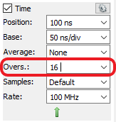
Oversampling acquires multiple captures, each with small shifts in the starting time. For a repetitive event this allows us to effectively get data points closer together. -
Measure the risetime, the time it takes to go from the low voltage state to the high voltage state.
| Show your worksheet to the instructor when you have completed both exercises. |
3. Your Turn
|
In the Introduction to Embedded Systems course that I teach at Whitworth University, students complete Your Turn assignments using repository template created through a GitHub Classroom assignment link on Canvas (our CMS). The directions that follow are intended for those students. However, an alternative link to a template is provided for non-Whitworth students. |
We can also make the action of a complete button press (depressed followed by a release) rotate through different blinking rates. This means that we need to keep track of additional information that reflects its history, not just the current status of the button. This information is called the state of the system. In this example there are two important state variables to store:
-
the current flash rate (which initially has two options: slow and fast)
-
the previous status of the button
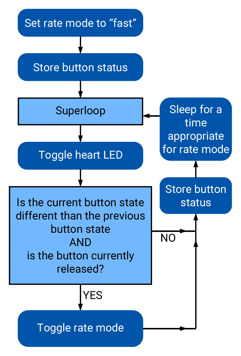
as well as the current status of the button. The flow diagram in Figure 5 gives an overview of the logic required to implement blink rate toggling with this state information.
The status of a GPIO can be represented as either true or false, so we will store that state in a boolean variable (specified with the keyword bool). The other state variable holds information about the flash rate mode. In the current program we have begin with two possible options for that, but you will soon extend that to a third option. Because it is countable an obvious choice is once again an integer variable. We could use the standard int for this, but to make the code easier for humans to understand we will instead use a special integer version: enum.
The name enum is short for enumerated. This is a word that means something is associated with a number. In this case we are going to write our program using human-friendly names to refer to the different flashing rate modes, but behind the scenes these will be stored as integers. The first thing we do is to define that enumeration:
enum rateState_t {FastMode, SlowMode};Our custom variable type is given the name rateState_t. It has only two possible values: FastMode and SlowMode. The computer treats these as if they were the numbers 0 (for FastMode) and 1 (for SlowMode).
A C convention is to end custom variable type names with _t and to write the possible value names of an enum in upper camel case.
|
Inside of the main function we will then declare a variable rateMode that is of this type and is initially set to the fast mode.
enum rateState_t rateMode = FastMode;The meaning of this is less ambiguous to a human reader of the code than the alternative version using the standard int:
int rateMode = 0;The previous program had an if…else statement with a simple condition. The state of the button was either 0 or 1. This time we will need to select among several options based on the value of rateMode. We could use a series of if statements to direct the code, but a better solution in C is the switch structure.
A switch structure begins by specifying the variable that we will be testing. We then specify the possible options using the case keyword. The code to be run if that option is selected follows and break; indicates where it ends. In our case this becomes
switch (rateMode) {
    case FastMode: k_msleep(FAST_SLEEP_TIME); break;
    case SlowMode: k_msleep(SLOW_SLEEP_TIME); break;
}
This code has been made compact so it displays better on the printed page or small screens. However, it is not necessary
to have the case statements written all on one line. The key thing is that the statements that are part of
a particular case begin after the colon (:) and end with break;. For example, one could write these over
multiple lines and use indentation to indicate the block.
switch (rateMode) {
    case FastMode:
        k_msleep(FAST_SLEEP_TIME);
        break;
    case SlowMode:
        k_msleep(SLOW_SLEEP_TIME);
        break;
}
This style is useful if there is more complex logic for each case. We will encounter situations like that latter in the course.
Next we have the compound condition “Is the current button state different than the previous button state AND is the button currently released?” We can break this into three questions:
-
Is the button currently released?
-
Is the current button state not equal to the previous button state?
-
Are the answers to questions 1 and 2 both yes?
We will now look at each these in turn, assuming the current state of the button is saved to currBtn and the previous state of the button to prevBtn.
| Question 1 |
Remembering that the button reads |
| Question 2 |
The NOT EQUAL logic operator in C is |
| Question 3 |
The question “Are the answers to questions 1 and 2 both yes” requires the AND logic operator. In C AND is written as |
if ((currBtn != prevBtn) && (!currBtn)) {-
Access the GitHub Classroom assignment link (found on Canvas) and create the repository for this assignment.
If you are not a Whitworth student in EN 173 you may access a starting template at https://github.com/EmbedUni/lab02-yt1. You will want to click on the Use this template button. -
Open the Source Control side bar in VS Code and clone the repository.
-
This repository already contains a
main.cwith the contents of Program 5. -
Add a build configuration and then build the application.
-
Flash it to your development board and verify that pushing BUTTON1 rotates between two different flashing rates.
-
Your task in this assignment is to add a third mode (
MediumMode) with a rate between slow and fast. Adapt the code so pressing the button rotates through all three modes (in the order fast, medium, and then slow, before starting over again at fast).
#include <zephyr/kernel.h>
#include <zephyr/drivers/gpio.h>

#define FAST_SLEEP_TIME   100
#define SLOW_SLEEP_TIME   500

/* Get node identifiers */
#define LED0_NI DT_ALIAS(led0)
#define BTN0_NI DT_ALIAS(sw0)

/* Get gpio specs */
const struct gpio_dt_spec led = GPIO_DT_SPEC_GET(LED0_NI, gpios);
const struct gpio_dt_spec button = GPIO_DT_SPEC_GET(BTN0_NI, gpios);

enum rateState_t {FastMode, SlowMode};

int main() {
    enum rateState_t rateMode = FastMode;
    bool prevBtn, currBtn;

    if (gpio_is_ready_dt(&led) && gpio_is_ready_dt(&button)) {
        gpio_pin_configure_dt(&led, GPIO_OUTPUT_ACTIVE);
        gpio_pin_configure_dt(&button, GPIO_INPUT);
    } else return -1;

    prevBtn = gpio_pin_get_dt(&button);
    while (true) {
        gpio_pin_toggle_dt(&led);
        currBtn = gpio_pin_get_dt(&button);
        if ((currBtn != prevBtn) && (!currBtn)) {
            switch (rateMode) {
              case FastMode: rateMode = SlowMode; break;
              case SlowMode: rateMode = FastMode; break;
            }
        }
        prevBtn = currBtn;
        switch (rateMode) {
            case FastMode: k_msleep(FAST_SLEEP_TIME); break;
            case SlowMode: k_msleep(SLOW_SLEEP_TIME); break;
        }
    }
}
Remember to update the README.md as well as main.c files. Push commits to the remote repository. The final commit should be the message “Done”.