
Lab 6: Analog input
1. Getting started with analog input
In this exercise you will read an analog input (created with a potentiometer). The value received by the microcontroller will be sent using the logger to the host computer via USB and viewed using a terminal program.
Unlike general digital input and output, only certain pins can be mapped to the ADC on the nRF52840, but which pins are mapped to particular channels is determined by the user. The available analog pins are given symbolic names, specified in Table 1.
| GPIO | Analog input name | Arduino label |
|---|---|---|
P0.02 |
AIN0 |
|
P0.03 |
AIN1 |
A0 |
P0.04 |
AIN2 |
A1 |
P0.05 |
AIN3 |
|
P0.28 |
AIN4 |
A2 |
P0.29 |
AIN5 |
A3 |
P0.30 |
AIN6 |
A4 |
P0.31 |
AIN7 |
A5 |
VDD |
VDD |
-
Create a new application.
-
Edit
prj.confto enable both logging and analog-to-digital conversion.Program 1. The ADC and logging modules must be enabled inprj.conf.CONFIG_LOG=y CONFIG_ADC=y -
Generate a build configuration and create an overlay.
-
Edit the overlay file.
Program 2. An ADC channel is specified and made available in the overlay./{ zephyr,user { (1) io-channels = <&adc 0>; (2) }; }; &adc { #address-cells = <1>; #size-cells = <0>; status = "okay"; channel@0 { reg = <0>; zephyr,reference = "ADC_REF_INTERNAL"; (3) zephyr,gain = "ADC_GAIN_1_6"; (4) zephyr,acquisition-time = <ADC_ACQ_TIME_DEFAULT>; zephyr,input-positive = <NRF_SAADC_AIN0>; (5) zephyr,resolution = <12>; (6) }; };1 The zephyr,usernode of the devicetree is a special node that does not require a corresponding binding file.2 Channel 0 of the ADC is connected to the io-channelsproperty.3 Uses a 0.6 V reference that is internal to the ADC. 4 Sets the gain to 1/6 so the voltage on the input pin is scaled to not exceed the reference voltage. There are additional limits on an input pin: its voltage should never fall below ground or exceed the board’s VDD (nominally 3.0 V). 5 If using the nRF52840, this connects P0.02 to this channel of the ADC. See Table 1. 6 Use the full 12-bit resolution of the ADC. The analog-to-digital converter (ADC) on the nRF52840 has a maximum resolution (in normal operating mode) of 12 bits. -
Enter Program 3 into
main.c.Program 3. Read an analog input and print its value in both raw and millivolt format.#include <zephyr/kernel.h> #include <zephyr/drivers/adc.h> #include <zephyr/logging/log.h> LOG_MODULE_REGISTER(Lab6_Program1, LOG_LEVEL_DBG); const struct adc_dt_spec adc_channel = ADC_DT_SPEC_GET(DT_PATH(zephyr_user)); (1) int main(void) { int err; uint16_t buf; (2) int val_mV; (3) struct adc_sequence pot_reading = { (4) .buffer = &buf, (5) .buffer_size = sizeof(buf) (6) }; if (!adc_is_ready_dt(&adc_channel)) { LOG_ERR("ADC controller device is not ready"); return -1; } err = adc_channel_setup_dt(&adc_channel); (7) if (err < 0) { LOG_ERR("Could not setup channel."); return -1; } err = adc_sequence_init_dt(&adc_channel, &pot_reading); (8) if (err < 0) { LOG_ERR("Could not initialize ADC sequence."); return -1; } while (true) { err = adc_read_dt(&adc_channel, &pot_reading); (9) if (err < 0) { LOG_ERR("Could not read"); continue; } val_mV = (int)buf; (10) err = adc_raw_to_millivolts_dt(&adc_channel, &val_mV); (11) if (err < 0) { LOG_INF("ADC reading: raw = %d", buf); } else { LOG_INF("ADC reading: raw = %d, volts = %d mV", buf, val_mV); } k_msleep(2000); } }1 The zephyr,usernode did not have a label or an alias. To refer to it, we needed to use its path. Devicetree names can include commas and dashes, put those must be changed to underscores when referring to them in C code. Thus thezephyr,usernode is referenced with the namezephyr_user.2 Declare an unsigned (non-negative) 16-bit integer variable to hold the raw reading from the ADC. 3 An intin Zephyr is a signed 32-bit integer.4 The ADC requires an adc_sequencestructure. This one is namedpot_reading(pot is common shorthand for potentiometer). There are additional elements of this structure that could be specified, but in this program only the essentials will be set:bufferandbuffer_size.5 When an &is placed before a variable name in C, it indicates that the memory address itself of this variable is retrieved, rather than the value stored at that location. By telling the ADC this memory address, it will be able to put values there (which we will access using the usual name, via the namebuf).6 It is possible for an ADC to read multiple values. When it does that, it starts writing the first value at the address specified by bufferand subsequent values are placed in the following memory addresses. The ADC needs to be told how many memory addresses have been set aside for this so it doesn’t write to a memory address that is being used for something else. Thesizeofreturns the number of bytes associated with a particular variable. For a 16-bit unsigned integer, that is 2 bytes.7 Preparing the ADC for use is a two-step process. First, the ADC channel is configured. 8 The second step is to link an adc_sequencestructure to the ADC channel.9 Calling adc_read_dttriggers the actual analog-to-digital conversion. That value is stored inbuf(remember thatpot_readingcontained its memory address).10 This is an example of type casting. It takes a 16-bit unsigned integer and reformats it as a 32-bit signed integer. At this point val_mVholds the same value asbuf, but in a different sized container.11 The memory location of val_mVis given toadc_raw_to_millivolts_dt. It uses this to read the raw value stored there. It then uses its knowledge of the ADC settings to convert that raw value to one in millivolts. The memory location is then used to updateval_mVso it instead has the value in millivolts. -
Make a connection between GND on the development board and the ground bus on a breadboard.
-
Make connection between VDD on the development board and a power bus on the breadboard. It will be more convenient if it is the power bus adjacent to the ground bus that you connected in the previous step.
-
Connect the black wire of the potentiometer to the ground bus and the red wire to the power bus.
-
Connect the green wire of the potentiometer to a terminal strip on the breadboard. Also make a connection from that terminal strip to P0.02.
-
Build your application and flash it to the development board.
-
Observing the log messages printed to the terminal, turn the potentiometer knob. The low end of the range should be close to 0 V and the high end of the range should be 3.0 V if you are powering your development board via USB.
-
Connect the 1+ flywire of the Analog Discovery to the same terminal strip as the green wire of the potentiometer.
-
Connect both the 1- and
 flywires to ground.
 -
Start Waveforms and open the Voltmeter application. Click Run to continuously update the readings.
-
Using the voltmeter as a guide, adjust the potentiometer knob until you produce a DC voltage of 1.5 V (as close as possible). Record the two analog input values reported by the microcontroller (the raw value and the millivolt value).
-
Repeat these measurements for potentiometer settings producing voltmeter readings of 0.1 V and 2.9 V.
1.1. Measuring light with a light-dependent-resistor
You will be using a light-dependent resistor (photocell). Your goal is to determine the best resistor to use in the voltage divider so you get maximum sensitivity under the conditions you might encounter indoors.
-
Construct a voltage divider consisting of a 10 kΩ resistor and the LDR, with the resistor connected to the power bus and the LDR connected to the ground bus. Connect a wire to the junction between the resistor and the LDR. The other end of the wire should go to P0.02.
-
Using Program 3, record the millivolt reading for the following conditions:
-
the LDR is covered
-
the LDR is exposed to bright light (such as the “flashlight” of a smartphone)
-
-
Repeat the light and dark measurements for two other resistors: 4.7 kΩ and 47 kΩ.
-
For the particular LDR that you have, which resistor should you choose to get the greatest difference between the light and dark readings?
1.2. Measuring temperature with an analog sensor
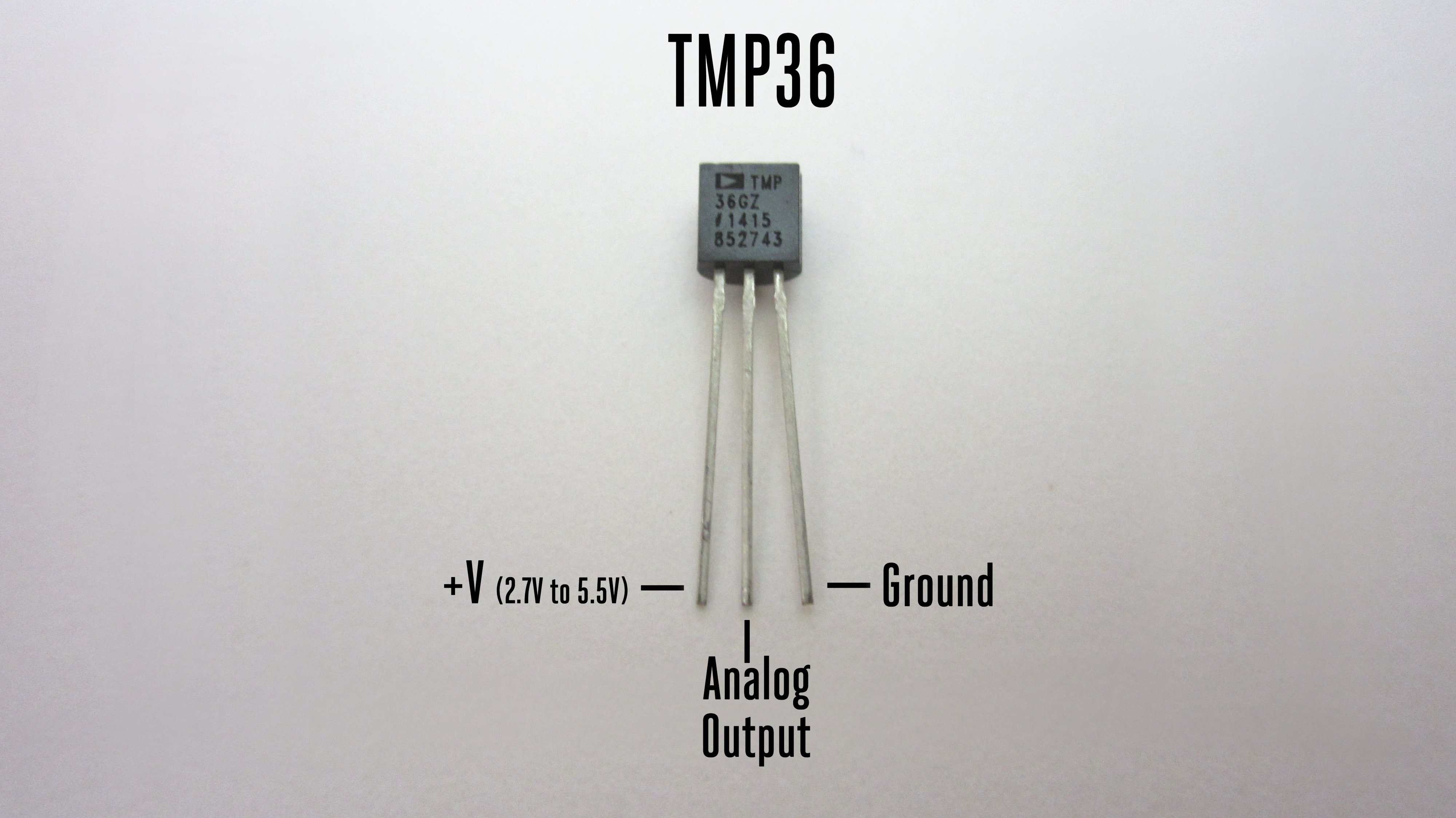
The TMP36 is an analog temperature sensor working over the range -40°C to +125°C. The TMP36 produces a voltage of 750 mV when it is at a temperature of 25°C. Each 1°C temperature increase causes the voltage to increase by 10 mV. It comes in a standard package called TO-92-3, as shown in Figure 1. Many other things come in the same package so carefully look for the TMP36 label in tiny print on its face.
Previous examples have used a gain setting of 1/6, permitting input voltages up to 3.0 V (VDD). If we are using this to measure room air temperatures we might never expect a temperature above 40°C. This means the highest voltage that should be produced by the TMP36 is 900 mV. The goal is to select a gain setting that brings 900 mV to under 600 mV (the internal voltage reference of the ADC), but as close to it as possible. Given the possible options, a gain of 1/2 is the best fit to our criteria.
The long jumper wires commonly used while prototyping can pick up electromagnetic noise on this scale, so we will reduce that noise through averaging. The ADC can be configured to make multiple measurements as part of a single read command. We can also improve performance clustering the wires going to the ADC, GND, and VDD. To do this, we will switch the analog input to AIN1 (P0.03).
The zephyr,user node is not the only place we can use an ADC. In this exercise you will begin the work that would be needed to create a device driver for the Analog Device’s TMP36. That requires creation of the appropriate binding file, similar to what was done previously with the servo.
-
Connect pin 1 of the TMP36 (the left leg when looking at its flat front) to the power bus strip. The power bus strip should be connected to the development board VDD.
-
Connect pin 2 of the TMP36 (the middle leg) to P0.03
-
Connect pin 3 of the TMP36 (the right leg) to the ground bus. As usual, the ground bus should also be connected to the development board GND.
-
Create a new application.
-
Create a new folder named
dtsat the top-level of your application (not inside any folder other than the one holding application itself). Inside of thedtsfolder create another folderbindings. -
Create a file named
adi,tmp36.yamlinside of thebindingsfolder. It is standard practice to name a binding file as follows: -
Begin with an abbreviated form of the manufacturer’s name. In this case the customary abbreviation for Analog Devices is
adi(the same as its stock ticker). -
This is followed by a comma and then the model of the device.
-
All of this is done using lowercase.
-
Add the following to that binding file:
description: Analog Devices analog temperature sensor TMP36 compatible: "adi,tmp36" include: sensor-device.yaml properties: io-channels: required: true description: ADC channel for temperature sensor vtemp25: type: int default: 750 description: | Temperature sensor voltage at 25 degrees Celsius in millivolts sensor-slope: type: int default: 10 description: | Temperature sensor slope in millivolts per degree Celsius -
Generate a build configuration and create an overlay.
-
Edit the overlay file. We are going to add the TMP36 using the binding just created.
&adc { #address-cells = <1>; #size-cells = <0>; status = "okay"; channel@0 { reg = <0>; zephyr,gain = "ADC_GAIN_1_2"; zephyr,reference = "ADC_REF_INTERNAL"; zephyr,acquisition-time = <ADC_ACQ_TIME_DEFAULT>; zephyr,input-positive = <NRF_SAADC_AIN1>; zephyr,resolution = <12>; }; }; /{ temp0: temp0 { compatible = "adi,tmp36"; io-channels = <&adc 0>; }; }; -
Edit
prj.confto enable analog-to-digital conversion, logging, and output of floating point numbers.CONFIG_ADC=y CONFIG_LOG=y CONFIG_CBPRINTF_FP_SUPPORT=y -
You are now ready for the actual application code in
main.c.Program 4. Measure temperature using a TMP36 analog sensor.#include <zephyr/kernel.h> #include <zephyr/drivers/adc.h> #include <zephyr/logging/log.h> #include <zephyr/devicetree.h> LOG_MODULE_REGISTER(AnalogTemp, LOG_LEVEL_DBG); #define NUM_ADC_READINGS 10 #define TMP36 DT_NODELABEL(temp0) const struct adc_dt_spec tmp36 = ADC_DT_SPEC_GET(TMP36); /* Use DT_PROP() to get volt-to-temp parameters */ #define MV_AT_25C DT_PROP(TMP36, vtemp25) #define MV_PER_DEG_C DT_PROP(TMP36, sensor_slope) int main(void) { int err; uint16_t buf[NUM_ADC_READINGS]; (1) int val_mV; float avg_mV; (2) float T_in_C; struct adc_sequence_options options = { (3) .extra_samplings = NUM_ADC_READINGS-1, (4) .interval_us = 100 (5) }; struct adc_sequence tmp_reading = { .options = &options, (6) .buffer = buf, .buffer_size = sizeof(buf) (7) }; if (!adc_is_ready_dt(&tmp36)) { LOG_ERR("ADC controller device is not ready"); return -1; } err = adc_channel_setup_dt(&tmp36); if (err < 0) { LOG_ERR("Could not setup channel."); return -1; } err = adc_sequence_init_dt(&tmp36, &tmp_reading); if (err < 0) { LOG_ERR("Could not initialize ADC sequence."); return -1; } while (true) { err = adc_read_dt(&tmp36, &tmp_reading); if (err < 0) { LOG_ERR("Could not read. Error code %d", err); k_msleep(2000); continue; } avg_mV = 0.0; (8) for (int i = 0; i < NUM_ADC_READINGS; i++) { (9) val_mV = (int)buf[i]; adc_raw_to_millivolts_dt(&tmp36, &val_mV); avg_mV = avg_mV + (float)val_mV; (10) } avg_mV = avg_mV/NUM_ADC_READINGS; (11) T_in_C = 25.0 + (avg_mV - (float)MV_AT_25C)/(float)MV_PER_DEG_C; (12) LOG_INF("T = %.1f deg C", T_in_C); (13) k_msleep(5000); } }1 The buffer for ADC values must now be an array because multiple values will be read. 2 A floatis required to store the average of multiple measurements because it will result in a non-integer value.3 A structure to hold optional values that can be used when configuring an adc_sequence.4 One measurement always take place in an ADC reading. This is the number of additional readings so it is one less than the total number of readings. 5 The time between the start of sequential ADC conversions, in microseconds. Note that it is not the time between the completion of one conversion and the beginning of the next. This means that if it is set to less than the time required for a single conversion to complete, an error will be generated. 6 The options previously stored are now added to the adc_sequencestructure.7 This is the size of the buffer (in bytes). 8 This variable will first be used to accumulate the sum of the measurement values. It must be set to 0 before those values are added to it. 9 A loop over all of the measurements. 10 Cast each measured millivolt value from an integer to a float before adding it to the accumulating sum. 11 The average is calculated by dividing the sum by the number of measurements. 12 Convert the average millivolt reading to a temperature using the sensor parameters. 13 The temperature is a floating point number so it must be displayed using the %fspecifier. The.1between the%and thefindicates that it should be displayed to the tenths place.
2. Revisiting digital input
In this exercise you will revisit digital input, using the potentiometer to create a variable voltage but with the input now configured as digital, rather than analog. You will observe the digital logic levels.
-
Connect VDD to the power bus on the breadboard, GND to the ground bus, and P0.02 to row 30.
-
Connect the potentiometer with the red lead to the power bus, the black lead to the ground bus, and the green lead to row 30.
-
Connect the 1+ flywire of the Analog Discovery 2 to row 30. Connect 1- and
to the ground bus. -
Create a new project containing Program 5. You will also need to generate an overlay defining P0.02 as a digital input called
ext_input(no pull-up or pull-down resistors are needed). -
Build and flash the application to your microcontroller.
-
Start Waveforms and open the Voltmeter application. Click Run to continuously update the readings.
-
Turn the potentiometer knob until the DC voltage reads 0.
-
Slowly turn the potentiometer knob until the LED turns on. Record the voltage.
-
Continue turning the potentiometer to produce an increasing voltage until the DC voltage reads 3.0 V.
-
Slowly turn the potentiometer knob the other way until the LED turns off. Record this voltage.
-
Starting from here, increase the voltage again until the LED turns on. Do you get the same voltage as you did the first time?
-
Decrease the voltage until the LED turns off. Is the voltage consistent with what you found earlier?
#include <zephyr/kernel.h>
#include <zephyr/drivers/gpio.h>

#define LED_NI  DT_ALIAS(led0)
#define EXT_INPUT_NI  DT_NODELABEL(ext_input)

const struct gpio_dt_spec led = GPIO_DT_SPEC_GET(LED_NI, gpios);
const struct gpio_dt_spec ext_input = GPIO_DT_SPEC_GET(EXT_INPUT_NI, gpios);

int main(void) {
    gpio_pin_configure_dt(&led, GPIO_OUTPUT_INACTIVE);
    gpio_pin_configure_dt(&ext_input, GPIO_INPUT);

    while (true) {
        if (gpio_pin_get_dt(&ext_input)) {
            gpio_pin_set_dt(&led, 1);
        } else {
            gpio_pin_set_dt(&led, 0);
        }
    }
}