
Lab 3: External digital inputs
1. Slide switches and momentary push buttons
1.1. Selecting external LEDs with a slide switch
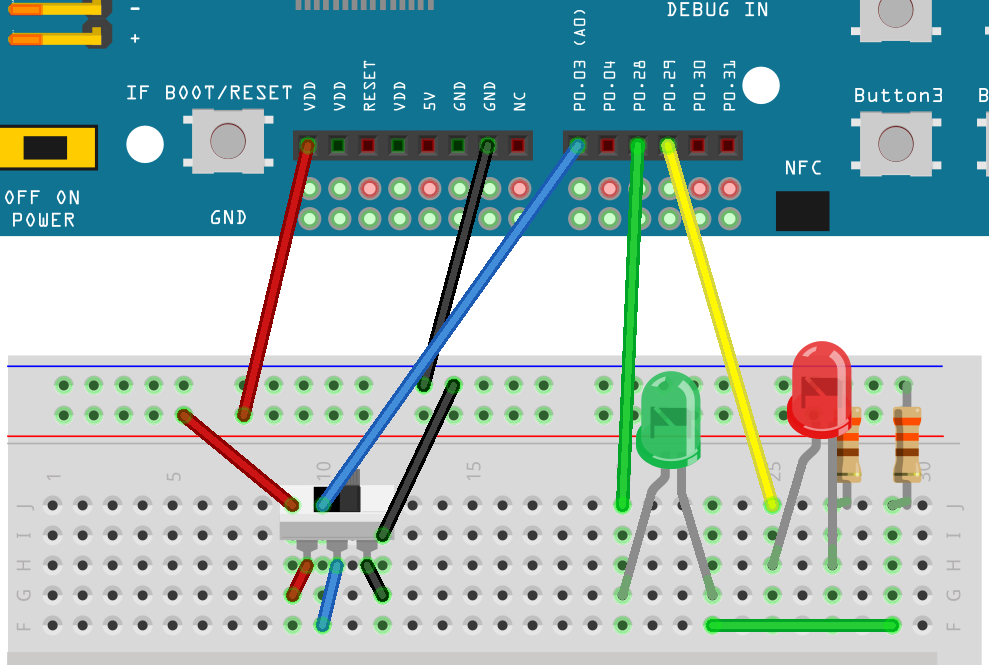
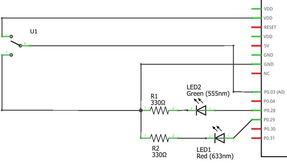
In this example a slide switch (single pole, double throw) is used to create either a high voltage or low voltage on a digital input. If the input is high, a red LED will flash. If the input is low, a green LED will flash.
Construct the circuit shown in Figure 1 (breadboard view) and Figure 2 (circuit diagram) on your breadboard. The apparent lengths of the LED legs in this diagram are solely due to how far they had to travel to reach their proper holes. The long leg of each LED should be connected to the microcontroller pins.
-
Create a new application and enter the code shown in Program 1 into
main.c.Program 1. Flash red or green LED depending on switch position.#include <zephyr/kernel.h> #include <zephyr/drivers/gpio.h> #include <zephyr/device.h> #define SLEEP_TIME_MS 200 /* Get node identifiers using label */ (1) #define RED_NI DT_NODELABEL(red_led) #define GREEN_NI DT_NODELABEL(green_led) #define SWITCH_NI DT_NODELABEL(slider) /* Get gpio specs */ const struct gpio_dt_spec redLED = GPIO_DT_SPEC_GET(RED_NI, gpios); const struct gpio_dt_spec greenLED = GPIO_DT_SPEC_GET(GREEN_NI, gpios); const struct gpio_dt_spec slideSwitch = GPIO_DT_SPEC_GET(SWITCH_NI, gpios); int main() { if (device_is_ready(redLED.port)) { (2) gpio_pin_configure_dt(&redLED, GPIO_OUTPUT_ACTIVE); gpio_pin_configure_dt(&greenLED, GPIO_OUTPUT_ACTIVE); gpio_pin_configure_dt(&slideSwitch, GPIO_INPUT); } else return -1; while (true) { if (gpio_pin_get_dt(&slideSwitch)) { (3) gpio_pin_toggle_dt(&redLED); k_msleep(SLEEP_TIME_MS); } else { gpio_pin_toggle_dt(&greenLED); k_msleep(SLEEP_TIME_MS); } } }1 It is possible to get node identifiers using node labels rather than using an alias. The alias approach is best when a program is meant to run on many different boards, each of which may have reasons for choosing other node labels for various components. However, if you are just developing for a single board then the node label approach avoids extra code in the overlay file. 2 All of the pins that were selected are on the same port. If the port controller is ready, it is ready for all of them. The device_is_readymethod is a more general test of readiness that works with both GPIO controllers and much more.3 Get the state of slide switch. A value of true(equivalent to 1) means the middle pin of the slide switch is connected to the high voltage. If that is the case, flash the red LED. Otherwise, flash the green LED. -
Select Add build configuration panel through the nRF Connect side bar and select our board as the target. Uncheck the Build after generating configuration box so the final button becomes Generate Configuration. Click on this button.
-
In the Actions section of the nRF Connect side panel, hover over the Devicetree entry to reveal the more options indicator (three dots) on the right. From that, select Create overlay.
-
Select Skip as the next step from the Overlay file created dialog.
-
Add the following to the
nrf52840dk_nrf52840.overlayfile that was created.Program 2. The overlay file allows us to configure both input and output pins./{ leds { red_led: led_4 { (1) gpios = <&gpio0 29 GPIO_ACTIVE_HIGH>; }; green_led: led_5 { gpios = <&gpio0 28 GPIO_ACTIVE_HIGH>; }; }; buttons { (2) slider: button_4 { (3) gpios = <&gpio0 3 GPIO_ACTIVE_HIGH>; (4) }; }; };1 Our first new node in the devicetree has a node identifier of led_4and a label ofred_led. We are using the label rather than an alias to access this node inmain.c.2 A buttonsection exists in the devicetree for GPIO inputs. We are adding an entry to this section.3 Our external slide switch is given the label sliderand has the node identifierbutton_4(button_0throughbutton_3are the buttons on the development board).4 This switch is connected to P0.03 and will have a truevalue when the voltage is high. -
You now want to perform a pristine build because the devicetree has been altered. The pristine build option can be found in the Actions section of the nRF Connect side panel. Hovering over Build will reveal the pristine build icon. Click on it.
-
Use the Flash action to send the program to your board. If everything has been done correctly, in one position of the switch the red LED will flash and if it is slid into the other position the green LED will flash.
| Demonstrate that you have successfully assembled this circuit and downloaded this program. |
| Leave the circuit connected. You will use the same hardware setup in the next exercise. |
1.2. Counting slide switch transitions
You will now count the number of times the switch has changed position. Zephyr’s logger module will be used to display the result on a computer through a terminal connection.
-
Create a new application.
-
Zephyr’s logger module is not enabled by default. We need to request that it be included in the application by editing the
prj.conffile. Add the following line to this file:CONFIG_LOG=y -
Add a build configuration and create a devicetree overlay. The contents should be the same as in the previous program (Program 2).
-
Enter the contents of Program 3 into
main.c.Program 3. Count switch transitions and display using logger.#include <zephyr/kernel.h> #include <zephyr/drivers/gpio.h> #include <zephyr/device.h> #include <zephyr/logging/log.h> (1) /* Get node identifiers using label */ #define RED_NI DT_NODELABEL(red_led) #define GREEN_NI DT_NODELABEL(green_led) #define SWITCH_NI DT_NODELABEL(slider) /* Get gpio specs */ const struct gpio_dt_spec redLED = GPIO_DT_SPEC_GET(RED_NI, gpios); const struct gpio_dt_spec greenLED = GPIO_DT_SPEC_GET(GREEN_NI, gpios); const struct gpio_dt_spec slideSwitch = GPIO_DT_SPEC_GET(SWITCH_NI, gpios); /* Register with logger */ LOG_MODULE_REGISTER(SlideCounter, LOG_LEVEL_DBG); (2) int main() { bool currentSwitchValue, previousSwitchValue; (3) int n = 0; // slide counts LOG_INF("Slider counter program starting"); (4) if (device_is_ready(redLED.port)) { gpio_pin_configure_dt(&redLED, GPIO_OUTPUT_ACTIVE); gpio_pin_configure_dt(&greenLED, GPIO_OUTPUT_INACTIVE); gpio_pin_configure_dt(&slideSwitch, GPIO_INPUT); } else { LOG_ERR("GPIO port is not ready"); (5) return -1; } k_msleep(100); previousSwitchValue = gpio_pin_get_dt(&slideSwitch); while (true) { currentSwitchValue = gpio_pin_get_dt(&slideSwitch); (6) if (currentSwitchValue != previousSwitchValue) { (7) n++; (8) previousSwitchValue = currentSwitchValue; LOG_INF("Slide counts = %d", n); (9) gpio_pin_toggle_dt(&redLED); gpio_pin_toggle_dt(&greenLED); } } }1 Using the logger module requires this header file. 2 We need to register our application with the logger module. The name given to our application in the logger is SlideCounterand all log levels (debug through error) will be displayed.3 The states of the switch will be held in boolean (true/false) variables. 4 Send a welcome message to logger so we will know when the code restarts. 5 Display an error message that might help us if the GPIO controller was not ready for us to configure the pins. 6 Reading the value of the switch once per time through the loop prevents logic problems that could result if the switch moved midway through the loop. 7 The logic operator !=means “not equal” so thisifstatement will be triggered when the switch changes from on to off or from off to on.8 This is shorthand for n = n + 1.9 Submit a log message with the %dreplaced by the value ofn. -
Build the application and flash it to your development board.
-
In the nRF Connect side panel:
-
Open the Connected Devices section.
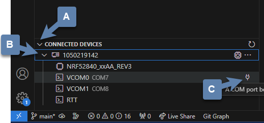 Figure 3. Open a terminal connection to the microcontroller.
 -
With only one microcontroller connected to the computer you should see only one entry. The number is the serial number of your particular development board. Expand this section.
-
Hover over the first VCOM entry to reveal the port icon on the right side. Click on this.
-
The default settings should be correct, so select the one option you are given.
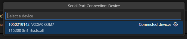 Figure 4. Select the default terminal settings (115200 baud).
-
-
Press the reset button on your development board. It is the push button set off by itself. You should see something similar to the following in the terminal window in VS Code.
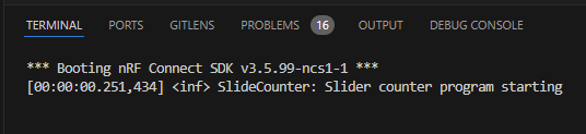 Figure 5. Start up logs from the slide counter application.
 -
Now slide the switch to a new position. You might have expected a log message to appear, but it did not. This is because the logger is a low-priority task and only sends messages to the terminal when the main application lets it (for example, by sleeping);
-
Modify the code in
main.c, addingk_msleep(1);as the first line inside thewhileloop. -
Build the revised program and flash the board again.
-
Test the revised program, sliding the switch back and forth. Does it always behave as expected?
With this configuration, the behavior when the button is released will be unpredictable. You need to modify the devicetree overlay to configure the input pin with an internal pull-down resistor (bringing the pin down to ground whenever the button is released).
In the buttons section of the overlay, replace the slider switch configuration with the following:
  buttons {
    pb: button_4 { (1)
      gpios = <&gpio0 3 (GPIO_ACTIVE_HIGH | GPIO_PULL_DOWN)>; (2)
    };
};| 1 | The node label was been changed to pb, short for push button. You will need to change your code in main.c accordingly. |
| 2 | The additional pull-down configuration is added using C’s bit-wise OR (|) to combine the two settings. We will learn about bit-wise logic later. |
You should observe that a single push of the button sometimes results in more than a change of 2 in the counts. This occurs because of something called button bounce.
-
Connect the flywire labeled 1+ (top left, orange) to the same column as the output pin of the button (the one that is connected to P0.03). Connect the flywire labeled 1- (bottom left, orange with white stripe) to the ground bus strip. Connect the ground (
 ) flywire to the ground bus strip.
 -
In the Time settings, change Position to 5 µs and Base to 2 µs/div.
-
In the Channel 1 settings, change Offset to -2 V and Range to 500 mV/div.
-
In the Trigger settings (above the graph), set Mode to Repeated and Normal and set Level to 2 V.
-
Click the Run acquisition button to repeatedly capture rising transitions without the need to restart.
-
Push the button, paying attention to the count and the WaveForms display. What do you observe?
-
Push and release the button until you observe the counter move forward to the expected count of 2. You will now save the corresponding oscilloscope capture to a Word document. Select and then select the Image tab. Under Comments, type “Button press, normal”. Uncheck Device, Serial Number, and Time. Then click on Copy to Clipboard.
-
Create a new Word document and paste your oscilloscope capture into it.
-
Now push and release the button until you observe the counter jumping forward by more than a count of 2. Export this oscilloscope capture with the comment “Button press, skip” and add it to your Word document.
-
In your Word document, write a brief description of the differences you observe in the two oscilloscope captures.
2. Photointerrupter
You will assemble a circuit with a photointerrupter that will be used to signal the microcontroller to turn on one of the internal LEDs whenever the beam is interrupted.
-
Build the circuit according to the diagram in Figure 6 and with the help of the pinout in Figure 7.
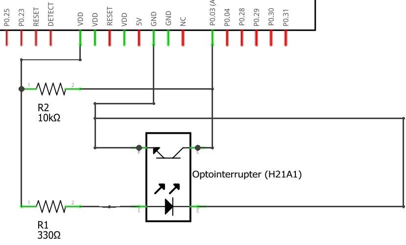 Figure 6. Diagram for the photointerrupter circuit.
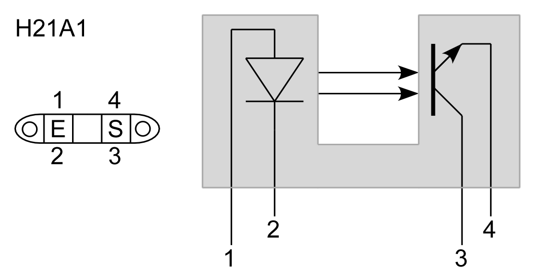 Figure 7. Pinout diagram for the photointerrupter.
 -
After you have assembled the circuit, create a new application.
-
Generate a build configuration and then create an overlay.
-
The overlay only needs to contain information about the photointerrupter. We are treating it as type of button.
/{ buttons { photointerrupter: button_4 { gpios = <&gpio0 3 GPIO_ACTIVE_HIGH>; }; }; }; -
Enter Program 5 into
main.c, build it, and then flash to your microcontroller.Program 5. LED indicates when photointerrupter is blocked.#include <zephyr/kernel.h> #include <zephyr/drivers/gpio.h> #define LED_NI DT_ALIAS(led0) #define PHOTO_NI DT_NODELABEL(photointerrupter) const struct gpio_dt_spec led = GPIO_DT_SPEC_GET(LED_NI, gpios); const struct gpio_dt_spec photo = GPIO_DT_SPEC_GET(PHOTO_NI, gpios); int main() { if (gpio_is_ready_dt(&led) && gpio_is_ready_dt(&photo)) { gpio_pin_configure_dt(&led, GPIO_OUTPUT_ACTIVE); gpio_pin_configure_dt(&photo, GPIO_INPUT); } else return -1; while (true) { if (gpio_pin_get_dt(&photo)) { gpio_pin_set_dt(&led, 1); } else { gpio_pin_set_dt(&led, 0); } } }
| Demonstrate your operating circuit. |
3. Your Turn
|
The directions that follow are intended for students in my Introduction to Embedded Systems course at Whitworth University. However, an alternative link to a template is provided for non-Whitworth students. |
Your task is to create a system that counts “letters” using a photointerrupter, displaying the count on an attached computer using the logger module. An internal button is used to reset the count to zero.
-
Access the GitHub Classroom link for this assignment on Blackboard and create a repository for your work.
If you are not a Whitworth student in EN 173 you may access a starting template at https://github.com/EmbedUni/lab03-yt1. You will want to click on the Use this template button. -
A code repository was created when you accessed the assignment. Copy the URL for the repository.
-
Open the Source Control side bar in VS Code and clone the repository.
-
Generate a build configuration and devicetree overlay. In the overlay file, add the code needed to configure the photointerrupter.
-
Enable the logger module in
prj.conf. -
Assemble the photointerrupter circuit on a breadboard.
-
Modify
main.cso it accomplishes the task described above. -
Test your program.
-
Update the
README.md.
| When your program and circuit are working successfully, remember to push the commits to the remote repository. Also, take a video of its successful operation and upload this to Blackboard. |