
Lab 10: Event-based interrupts
1. Reducing button latency with interrupts
Last session you monitored the status of the button using polling. This meant that sometimes pushes were missed because the processor was busy waiting and did not check while it was down. Other times it was detected, but this took a while (and the latency was quite variable). Program 1 changes how the state of the button is monitored. It uses an interrupt to determine when it has been pushed and this causes the processor to stop what it was doing and switch to dealing with the button push instead.
-
Connect a green LED and 330 Ω resistor in series between P0.28 and ground.
-
Connect a button so that it connects P0.03 to VDD when pressed.
-
Create a new application with an overlay that allows the use of P0.28 to control an external LED. The button portion of the overlay defines P0.03 as an input and should also enable the internal pull-down resistor.
-
Edit the
main.cfile to match the code in Program 1.
| 1 | This is a structure that holds the information needed to set up the interrupt. |
| 2 | This initializes the callback structure with the function to call when the button is pressed. The bit associated with this pin is set in the last argument. |
| 3 | This adds the callback to the GPIO port. |
| 4 | This sets up the interrupt to trigger when the button is pressed. The interrupt is triggered on the rising edge. |
-
Use the same oscilloscope settings as with the previous latency measurements (in Lab 9).
-
Click Single followed by pushing the momentary push button. Compare this oscilloscope capture to what you observed before. You should notice that the latency is decreased substantially.
-
The decrease in latency is so great that you need to change your oscilloscope settings so you can make some worthwhile measurements. Change the Time base setting to 1 us/div. The old setting was 50 ms (0.050 seconds) and this new setting is 10-6 seconds, a reduction by a factor of 50,000. The Position should also be zero in the Time settings.
-
Click Single followed by pushing the momentary push button. You should now be able to measure the latency. Do this a total of ten times.
-
Summarize these results by identifying the maximum latency, the minimum latency, and the average latency.
2. Counting button presses
The arguments of an ISR are strictly defined by Zephyr and depend on the the type of interrupt. The two most common types are time-based and event-based. The arguments for these are:
-
time-based interrupt:
void timerHandler(struct k_timer *timer) -
event-based interrupt:
void buttonHandler(const struct device *dev, struct gpio_callback *cb, uint32_t pins)
We need to use global variables (variables declared outside of the main function) if we want inputs or outputs. The example in Program 2 shows this (and assumes you still have the same circuit connected as in the previous part, though the green LED won’t be used this time). The program prints the number of times the button has been pressed to the computer. Communication is one of those time-consuming operations that should never occur in an ISR but Zephyr’s logging module is designed to be safe to use in an ISR. We have specified what should be sent to the computer within the ISR, but the logger will wait until it is safe to send the message. Lower level methods of printing to the computer would not be safe to use in an ISR. In those cases you would need to set a flag (a boolean variable) in the ISR and then check that flag in the main loop to determine if the button has been pressed.
You will see that our counting variable has the keyword volatile added in front of it in the declaration. This tells the compiler that it can’t assume the value is unchanging in normal program context. Sometimes compilers will simplify code and use a local copy of a variable rather than directly access the real memory location if the code looks like the value is unchanged. However, an ISR can cause it to change unexpectedly.
| When you have observed the behavior of this circuit, discuss it with your instructor. |
3. Counting button presses with a better debounce
You should have observed problems with button bounce in the previous program. We will use a timer to implement a good software solution to bounce.
-
Add the following to the top of the file (after the
#includestatements):#define DEBOUNCE_TIME_MS 100 K_TIMER_DEFINE(debounce_timer, NULL, NULL); -
Add the following as the first line inside of the
mainfunction:k_timer_start(&debounce_timer, K_MSEC(DEBOUNCE_TIME_MS), K_FOREVER); -
Replace
buttonPressedwith the following:void buttonPressed(const struct device *dev, struct gpio_callback *cb, uint32_t pins) { if (k_timer_status_get(&debounce_timer) == 1) { (1) numPresses++; LOG_INF("Button pressed %d times", numPresses); k_timer_start(&debounce_timer, K_MSEC(DEBOUNCE_TIME_MS), K_FOREVER); (2) } }1 This checks if the timer is still running. If it is, the button press is ignored. 2 This restarts the timer so that the next button press will be detected after the debounce time has passed.
| When you have observed the behavior of this circuit, discuss it with your instructor. |
4. Averaging with resistors and capacitors
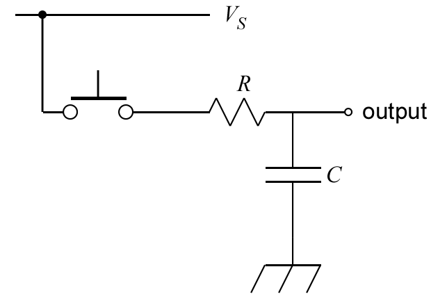
A resistor and a capacitor connected in series can create a filter. The output point is at the junction between the two. If the resistor and capacitor are connected such that the capacitor has one leg connected to ground then this is known as a low-pass filter. It allows low frequency signals to pass through and reduces high frequency signals. You can also think of this as averaging the signal over a time given by R times C.
On the other hand, if the resistor is the component that has one leg connected to ground then this is known as a high-pass filter. It reduces low frequency signals and allows high frequency signals to pass through to the output. We won’t be using a high-pass filter in today’s activities, but you should know that the behavior depends on the order that you connect these two components.
You will use a low-pass filter to debounce a push button using hardware rather than software, as shown in Figure 1.
-
Reopen the application with Program 2 (counting button presses with an ISR but no software debounce).
-
Place a push button on your breadboard and connect one of its pins to VDD.
-
Connect a diagonally located pin on the push button to a 10 kΩ resistor.
-
The other leg of the resistor should be connected to P0.03 and the long leg of a 10 µF capacitor. The short leg of the capacitor should be connected to ground.
-
Use the oscilloscope to observe the output of the low-pass filter (1+ to the junction between the resistor and capacitor, 1- to ground, and
 to ground).
 -
In the Trigger settings (above the graph), set Mode to Repeated and Normal and set Level to 2 V.
-
In the Channel 1 settings, change Offset to -2 V and Range to 500 mV/div.
-
Adjust the Time settings to capture details of the off-to-on transition when the button is pressed.
-
Click the Run acquisition button to repeatedly capture rising transitions without the need to restart.
-
Push the button, paying attention to the button counts and the WaveForms display. What do you observe?
-
Now observe what happens when you change the resistance. Replace the 10 kΩ resistor with a 1.5 kΩ resistor (brown-green-red). What differences do you observe on the oscilloscope and its reliability in counting only once per button push?
-
Replace the resistor with a 330 Ω one. What differences do you observe on the oscilloscope and its reliability in counting only once per button push?
| When you have finished your observations, discuss the results with the instructor. |
5. Your Turn
5.1. Interrupts from analog sources
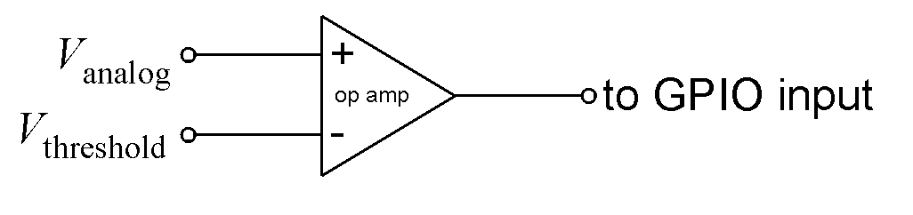
You will use a comparator circuit with an analog input so that if its value exceeds some threshold, a digital signal will be generated, triggering an interrupt. In this case, you will monitor the output of the TMP36 temperature sensor. An interrupt will be triggered if the temperature exceeds 27°C.
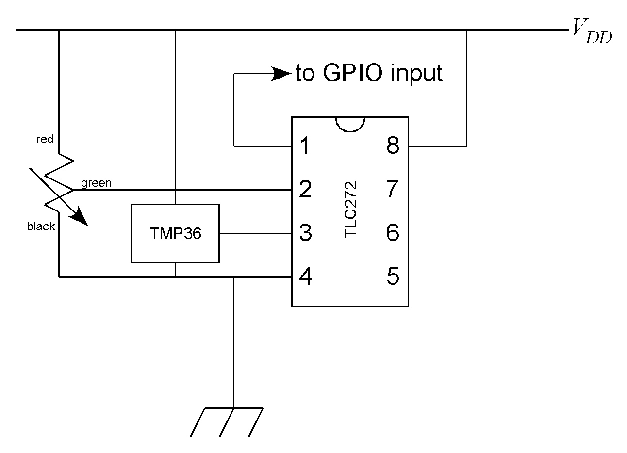
We will use the TLC272 op amp to create a comparator. This is an operational amplifier capable of running from the +3.3 V available from the microcontroller. The traditional circuit diagram for this is shown in Figure 2. This diagram omits the power supply and ground connections to the TLC272 (because experts know they are implied). Those connections are essential!
Discrete resistors could be chosen to set the threshold voltage (using the voltage divider equation seen earlier in this course). Or, instead of trying to find the perfect resistors, you can just replace the two resistors with a potentiometer and adjust the knob until you get the desired voltage. This is shown in the pin connection diagram, Figure 3.
Get the GitHub Classroom link from Blackboard.
Write a program that flashes LED4, on for 0.25 s and off for 0.25 s, using a timer with polling. Set up an interrupt to turn on LED1 if the temperature rises across the threshold. Set up a second interrupt to turn on LED2 and turn off LED1 if the temperature falls below the threshold. This means that LED1 indicates that it is currently too hot and LED2 tells us that the temperature may be fine now but was too hot at some time in the past.
| When your program and circuit are working, create a video demonstrating this. |
5.2. Night light
In this assignment you will demonstrate your ability to use both event- and time-based interrupts.
Get the GitHub Classroom link from Blackboard.
You will use an LDR to detect light levels. When the light drops below normal room lighting levels, the microcontroller will turn on an LED for 30 seconds (though in actually operation we would want a longer time, say 10-15 minutes). An external push button can be used to turn off the LED sooner.
You are to demonstrate your ability to use appropriate microcontroller design for responsive programming so you may not use the k_msleep commands for timing purposes. You should use one or more of the following: time-based interrupts, event-based interrupts, and hardware debounce.
| When your program and circuit are working, create a video demonstrating this. |