
Lab 1: Getting Started
1. Installing the tools
1.1. nRF Command Line Tools
Nordic Semiconductor provides a collection of tools in a package called nRF Command Line Tools that perform important tasks including the transfer of a program from your development computer to the microcontroller. We will not use them directly, but they are required for the other tools that we will use.
-
Download the nRF Command Line Tools from Nordic Semiconductor.
-
Install the tools. This also includes a separate installer for the required SEGGER J-Link software. It is important to select the option to install legacy USB drivers, particularly if you are using a freshly unpackaged nRF52840 DK board. They frequently ship with outdated firmware that requires these drivers.
-
If this is your first time to use a particular nRF52840 DK board, you will need to update the firmware on the board. This is done by running J-Link Commander after the nRF52840 DK is connected to the computer via USB. You should get a message that the firmware is out of date and be given the option to update it. When it is done, you can close J-Link Commander.
1.2. Visual Studio Code
We will be using Visual Studio Code throughout these activities. If you do not already have it installed, download it from https://code.visualstudio.com/.
Once you have VS Code running, you need to install several extensions:
-
Live Share (only required for pair programming activities)
You can install by following the links above or from within VS Code using the Extensions side bar. You open this by clicking on the Extensions icon in the Activity bar.
From the Extensions side bar you can search for the extensions listed above and then install from their page within VS Code.
1.3. Select an nRF Connect toolchain and SDK
-
Open the nRF Connect side bar by clicking on its icon in the Activity bar.
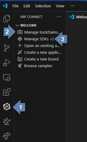 Figure 2. Manage the nRF Connect toolchain and SDK from the nRF Connect side bar.
 -
Click on Manage Toolchains and then select the Install Toolchain action.
-
These guides were tested using v2.6.2. Avoid using a more recent version as it may not be compatible with the directions provided.
-
Once all selections have been made, it triggers a substantial download and install process so be prepared to wait for several minutes.
-
-
Click on Manage SDKs and then select the Install SDK action.
-
These guides were tested using SDK 2.6.2. You want a version that matches that of the toolchain you just installed. Avoid
mainor numbered versions ending in-devor-csas these are not intended for widespread use. -
You will be asked to select a location for the SDK. The goal is to have a short path name and avoid folder names that have spaces.
-
1.4. Git and GitHub
We will be using Git throughout these activities. If you do not already have it installed, download it from https://git-scm.com/downloads/.
You also need a GitHub account.
After you have installed Git and created a GitHub account, open a terminal in VS Code by typing Ctrl+`. Note that this is the left single quote, typically located on the same key as ~. It is not the right single quote/apostrophe (located on the same key as "). Begin by verifying that Git is installed and accessible.
git --versionIf you see a version number, Git is installed.
You are now ready to tell the computer about the GitHub username that you are using and your email address.
git config --global user.name "yourusername" (1)
git config --global user.email "email@youremail.com" (2)| 1 | yourusername should replaced with your GitHub username. |
| 2 | email@youremail.com should be replaced with the email address associated with your GitHub account. |
2. An embedded “Hello, world”
On a general purpose computer the stereotypical first program in a language displays Hello, world! on the screen. In the world of microcontrollers the equivalent is to flash an LED. This is also called a heartbeat program. It is a simple way to indicate that your microcontroller is alive and you are able to transfer a simple program to it. Most development boards will have one or more integrated LEDs, so no external connections are necessary. The Nordic Semiconductor nRF52840 DK that will be our example development board has four integrated LEDs. The first program will flash one of these, labeled LED1, off and on forever (or as long as the microcontroller is powered). Flow charts are a useful tool for planning and documenting code, so before we jump into the code itself we start with a flow chart for this first program.
2.1. Creating a new application
-
Create a folder to hold all of your programs that will be associated with this series of lab guides. It should be close to the root of a drive and have a short name that is all lowercase and does not contain any spaces. An example would be
C:\embedlabs. -
Open the nRF Connect side bar by clicking on its icon in the Activity bar.
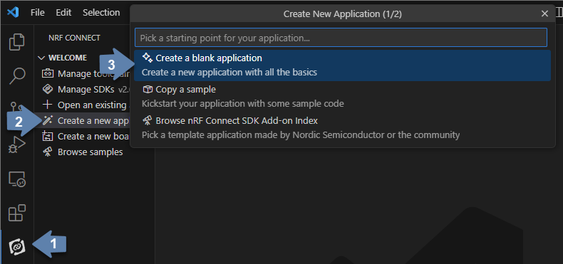 Figure 3. Create a new application from the nRF Connect side bar.
 -
Select Create a new application from the Welcome section.
-
Enter the name of the folder you have selected to store your programs and then the name of the folder for this particular activity (for example,
C:\embedlabs\lab1-prog1).
2.2. Entering the code
Replace the contents of main.c (in the src folder) with the following code. You are encouraged to type the code from these lab guides into the editor yourself; don’t copy and paste it. You will pay more attention to the details of the code and learn it better if you do this.
/********************************
 * Heartbeat program
 *
 * Flashes an internal LED
 *******************************/
#include <zephyr/kernel.h>    (1)
#include <zephyr/drivers/gpio.h>

#define LED0_NI DT_ALIAS(led0)    (2)
const struct gpio_dt_spec led = GPIO_DT_SPEC_GET(LED0_NI, gpios);  (3)

int main(void) {  (4)
	gpio_pin_configure_dt(&led, GPIO_OUTPUT_ACTIVE);  (5)
	while (true) {
        gpio_pin_set_dt(&led,1); // 1 = ACTIVE = ON
        k_msleep(250);
        gpio_pin_set_dt(&led,0); // 0 = INACTIVE = OFF
        k_msleep(250);
    }
}| 1 | Zephyr is designed to be lightweight so only the components you need are included. These import Zephyr’s Kernel and GPIO APIs. |
| 2 | Information about the hardware is stored in something called the devicetree. This looks up the node identifier for the LED associated with the alias led0. |
| 3 | This creates a container called led that holds information about a GPIO pin. |
| 4 | The Zephyr RTOS looks for a user-defined function called main to run after it completes its start-up. This is often the heart of your application. |
| 5 | The GPIO pin linked to LED1 is configured as an output and set to be in the active (on) state. |
2.3. Building and flashing the application
After you have entered the code (and saved it), it is necessary to compile it. This transforms it from relatively human-friendly C code into microcontroller-friendly machine language. That machine language depends on the particular microcontroller so the next step is to specify the build configuration.
-
Open the nRF Connect side bar.
-
In the APPLICATIONS section, click on Add build configuration under the name of your application.
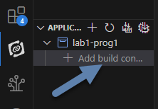 Figure 4. Add a build configuration from the nRF Connect side bar.
 -
Next, set the board target to match your microcontroller. If you are using the nRF52840 DK board you should select
nrf52840dk_nrf52840.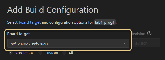 Figure 5. Add a build configuration from the nRF Connect side bar.
 -
Scroll to the bottom of this window and verify that the box before Build after generating configuration is checked.
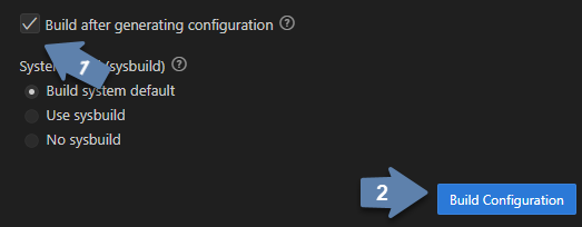 Figure 6. Set build after configuration option.
 -
Finish by clicking the Build Configuration button. The initial generation of a configuration and building of an application may take several minutes.
-
After a build configuration has been generated you will have new entries in the nRF Connect side bar. These new sections are labeled BUILD and ACTIONS.
-
If you get an error message related to your code, try to find the error in the
main.cfile. After fixing it, save the file and click on the Build action. This will go much faster than the original build process. -
Connect the microcontroller to the computer via a USB cable. The nRF52840 DK board has two micro USB ports. You want to use the one labeled IMCU USB.
-
Turn on the microcontroller via the ON/OFF switch on a corner of the board near the USB connection. Shortly after you do this you should observe that a section called CONNECTED DEVICES in the nRF Connect side bar is a new numbered entry (corresponding to the serial number of your board).
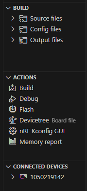 Figure 7. New sections are available in nRF Connect after selecting a build configuration and attaching a microcontroller.
 -
With a connected and powered microcontroller, you are now ready to transfer the program to it. Click on the Flash action.
-
If you get an error message related to flashing, under CONNECTED DEVICES (in the nRF Connect side bar), reveal the more actions menu by hovering over the righthand side of the entry for your board (a long number). Select Recover Board. This will reset the board and you can try flashing again.
-
If all goes well LED1 on your development board will begin to flash twice a second.
| Demonstrate that you have successfully compiled and run the embedded system “Hello, world” program. |
2.4. Documenting the first program
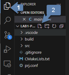
Create a new file called README.md in the top level folder (at the same level as the prj.conf file). To do this:
-
open the Explorer side bar,
-
click in the empty area below
proj.confto select the top level folder, -
hover over the title of this application (LAB1-PROJ1 if you followed the naming suggestions) to reveal more options,
-
click on the New file… icon, and
-
name this file
README.md.
This is where you will put some human-friendly documentation using a simple and widely used markup language called Markdown. We will also supplement Markdown with mermaid, a diagram-drawing language that will let us include graphics like flowcharts in our documentation.
Before you start adding contents to this file, turn on VS Code’s Markdown previewer by clicking on the Open Preview to the Side button (or type Ctrl+k and then v).
Entering the following code into the README.md file.
# Program 1: Heartbeat                              (1)
**Author:** John M. Larkin <jlarkin@whitworth.edu>  (2)

**Date:** December 31, 2024

**Modified by:**

**Date:**

**Purpose:** This program flashes an internal LED on the nRF52840 DK

## Configuration
Uses default devicetree configuration.

## Hardware                                     (3)
### Internal
* LED1 (digital output)                         (4)

## Flow
```mermaid                                      (5)
graph LR                                        (6)
  A("main()") --> B[Initialize LED1]
  B --> C{Is it true?}                          (7)
  C --> |yes| D[Turn on LED1]                   (8)
  D --> E([Sleep 250 ms])
  E --> F[Turn off LED1]
  F --> G([Sleep 250 ms])
  G --> C
```| 1 | Section headings are created in Markdown by starting a line with one or more # followed by a space and then the name of the section. A top-level section is one #, a second-level section starts with ##, and so forth. |
| 2 | Markdown puts text in bold if it is surrounded by **. It formats something as a click-able email link or URL if it is inside of < and >. Also, this line ends with two space characters. This creates a line break. Otherwise, the next line would be wrapped as a continuation of this line. |
| 3 | Our microcontroller will nearly always be connected to additional components. Part of good documentation will be describe those in the README file. |
| 4 | An itemized list has items that start with *, then a space, and that is followed by the description of the item. The space between * and the description is required. |
| 5 | The start of a mermaid code block begins with ```mermaid. |
| 6 | This flowchart is arranged from left to right. Another common arrangement is top to bottom (TB). |
| 7 | Nodes are named (the letters) and labeled (the text inside the various delimiters). Connections between nodes are given by -->. Different delimiters create different shapes of nodes. Conditional branching is traditionally inside of a diamond, created in mermaid with { and } delimiters. |
| 8 | Text can be place along a connecting line by placing it inside of a pair of | after the connector code (-->). |
2.5. Modifying the first program
Create a new application called cycle-blinky. In this project, create a README.md file. Use the README file for Program 1 as a template and modify as appropriate.
Create a flow chart for a program that would light the four integrated LEDs in the sequence LED1 → LED2 → LED3 → LED4 (and then repeat forever). Each LED should be lit for 0.25 s and it should appear that only one is on at a time (though there might actually be some very small overlap).
Starting with Program 1, change the code so that it implements the logic shown in the flow chart created for Exercise 1.1.
| Show your flow chart and working program when you are done. |
3. Extending the “Hello, world” program
The next challenge is to modify the “Hello, world” program to produce a more complicated LED blinking behavior. It will flash the leftmost LED five times and then flash the rightmost LED five times, and then repeat forever. The flow chart for this program is shown in Figure 10.
The code to implement this flow chart uses while loops that test for a condition. While the condition is true, the content of the loop is repeated. Create a new application (two-hearts) with this code and verify that it works as claimed.
while loops with blinking LEDs./********************************
* Left-right alternating blink
*
* Flashes left LED 5 times, then
* right LED 5 times. Repeat.
*******************************/
#include <zephyr/kernel.h>
#include <zephyr/drivers/gpio.h>
#define SLEEP_TIME_MS 250 (1)
#define LED0_NI DT_ALIAS(led0)
#define LED1_NI DT_ALIAS(led1)
const struct gpio_dt_spec leftLED = GPIO_DT_SPEC_GET(LED0_NI, gpios); (2)
const struct gpio_dt_spec rightLED = GPIO_DT_SPEC_GET(LED1_NI, gpios);
int main(void) {
int i = 0; (3)
gpio_pin_configure_dt(&leftLED, GPIO_OUTPUT_INACTIVE); (4)
gpio_pin_configure_dt(&rightLED, GPIO_OUTPUT_INACTIVE);
while (true) {
while (i<10) { // Flash the left LED five times
gpio_pin_toggle_dt(&leftLED); (5)
k_msleep(SLEEP_TIME_MS);
i = i + 1;
} (6)
while (i>0) { // Flash the right LED five times
gpio_pin_toggle_dt(&rightLED); (7)
k_msleep(SLEEP_TIME_MS);
i = i - 1;
} (8)
} (9)
}| 1 | The #define pre-compiler directive associates a name, SLEEP_TIME_MS, with a value, 250. Before the program is compiled, the pre-compiler will replace all occurrences of SLEEP_TIME_MS with its value. This means that no variable memory space is associated with SLEEP_TIME_MS. In this program SLEEP_TIME is used to control the on/off time for the LEDs. If a different on/off time was desired, only this definition would need to be changed rather than hunting through the code for all occurrences of a particular number. |
| 2 | There is usually only one connection to any particular hardware element. Therefore, our usual design style will be to declare all objects that connect to hardware outside of the main function. This means that they are global variables accessible by any function. |
| 3 | The integer variable i is declared within the main function. This means that this particular definition of i is local. We will explore this in more detail later. |
| 4 | The main function is called after the rest of the Zephyr RTOS initialization has finished. We want to wait until that is completed before we attempt to configure any hardware. Here the pins connected to the LEDs are configured as outputs and initially are turned off (inactive). |
| 5 | The inner while loop for flashing the left LED begins here. This also illustrates the toggle method a digital output. Toggle changes the state from off to on or from on to off. Doing this twice is one flash of the LED. That is why the loop runs 10 times to flash the LED five times. |
| 6 | The while loop for flashing the left LED ends here. If i is less than 10, jump up to the top of this loop. |
| 7 | The inner while loop for flashing the right LED begins here. |
| 8 | The while loop for flashing the right LED ends here. If i is greater than 0, jump up to the top of this loop. |
| 9 | The never-ending outer while loop repeats when it reaches this point. |
3.1. Preprocessor definitions make code easier to read
Rather than putting specific numbers into your code where they are actually used, a good design approach is to instead associate those numbers with symbolic names. Those symbolic definitions should be put in one place so they are easy to find. This may not seem that important with small programs, but as your programs grow in complexity it will be a helpful habit.
We can use a preprocessor directive to do this. As you may recall, the first step of the build process is to have the preprocessor manipulate your source code file before it is passed to the compiler. The #define directive is the particular method we will use for this task. It allows us to create find-and-replace rules. In the heart rate selector program we will have the following find-and-replace rules:
#define SLEEP_TIME_MS 250After the #define directive we give a symbolic name (our convention will be to write this in all upper case with underscores between words, a formatting called upper snake case). This is followed by a space and then the text we want to have replace that symbolic name.
Later in the code the k_msleep command for fast flashing is written using the symbolic names:
k_msleep(SLEEP_TIME_MS);but this is not what the compiler will see. Instead the preprocessor will replace the symbolic name with its value so the compiler gets:
k_msleep(250);4. Your Turn
|
In the Introduction to Embedded Systems course that I teach at Whitworth University, students complete Your Turn assignments using repository template created through a GitHub Classroom assignment link on Blackboard (our CMS). The directions that follow are intended for those students. However, an alternative link to a template is provided for non-Whitworth students. |
-
You need to begin by accessing the GitHub Classroom assignment link (as found on Blackboard).
If you are not a Whitworth student in EN 173 you may access a starting template at https://github.com/EmbedUni/lab01-yt1. You will want to click on the Use this template button. -
A code repository was created for you when you accessed the assignment. Copy the URL for the repository.
-
Open the Source Control side bar in VS Code.
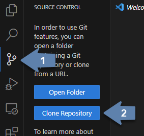 Figure 11. Clone a repository from the Source Control side bar.
 -
Click on Clone Repository.
-
Paste the URL you copied into the box that opens up.
-
Start with the
README.mdfile. Your first task is to update the flow chart so it describes the logic needed to do the following:-
Flash the left LED 10 times with on/off times of 0.5 s.
-
Then flash the right LED 5 times with on/off times of 0.25 s.
-
Then repeat (forever).
-
-
Update the rest of the
README.mdfile. -
Click on the Source Control icon in the left side bar to open the Source Control panel. There should be a section labeled Changes that lists
README.md. Hover over this line and then select the plus icon to stage the changes. -
Go to the Message box and enter a short description of the changes that were made. Something like “Updated flow chart” would be appropriate. Then press Ctrl+Enter to commit this change (make it part of the tracked history of this project).
-
Next to the name of the project you should see an up arrow and the number 1 (if you have only made one commit). Click on this to send these changes off to GitHub (this is called a “push” because it is going from your computer to the remote repository).
-
Update
main.cso it implements the logic shown in the flow chart. You may only use programming constructs introduced so far in this course (soforloops are forbidden). -
Again, commit these changes and push to the remote repository.
-
Specify the correct build configuration and then build the application.
-
Flash the code to the microcontroller for testing. Does it do what it is supposed to do?
-
If there are problems, fix those. Once everything works properly, edit the
README.mdfile and add a `Completed: ` line with the current date and time. -
Stage all changes and commit with the message “Done”.
The process for this assignment is similar to the previous one but there is a new GitHub Classroom link.
| If you are not a Whitworth student in EN 173 you may access a starting template at https://github.com/EmbedUni/lab01-yt1. |
Your task is to modify the program so that it:
-
Flashes the left LED ten times in a row, but the time of each flash increases, starting from 0.1 s and going up to 1.0 s, in steps of 0.1 s.
-
Then flashes the right LED five times in a row, but the time of each flash decreases, starting from 1.0 s and decreasing in 0.2 s steps to 0.2 s.
-
Repeats forever.
-
Use no more than four
k_msleepcommands. -
Uses
whileloops (only C commands already encountered in the course are allowed so things likeforloops and user-defined functions are forbidden).
Remember to update the README.md as well as main.c files. Push commits to the remote repository. The final commit should be the message “Done”.